The wiring of the turn signals is not immediately intuitive.
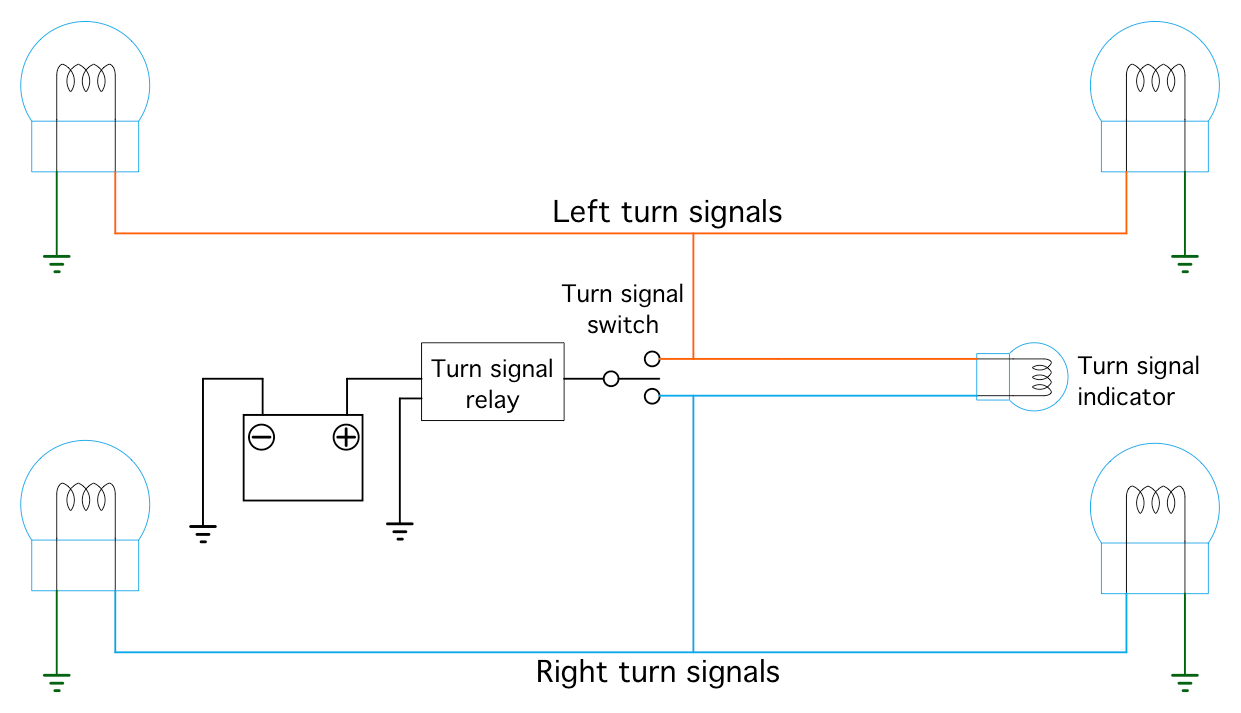
Here’s the full electrical circuit of the turn signals, minus the ignition switch and fuses:
Here’s the electrical path when the right turn signals are activated:
Note that the power for the dash indictator goes through the alternate
side main signals. The alternate side signals don’t light because
the power is split between them, and voltage(current) limited by the
dash indicator that’s in series with them. The two main lamps
in parallel equates to half the resistance, so there’s still plenty
of power remaining to light the indicator lamp.
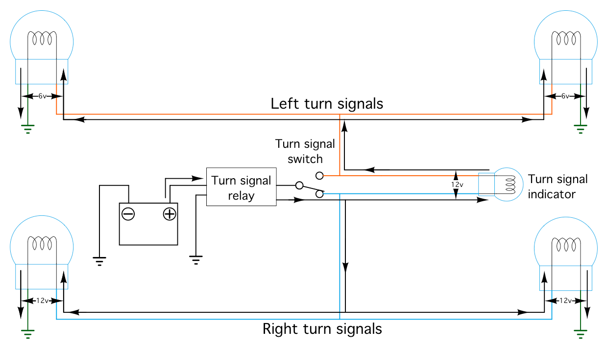
This diagram is a
little wrong, it’s simplified down to “volts” because
it’s close enough and gets the point across.
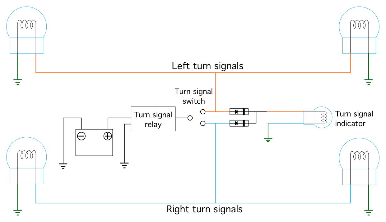
LED turn signals create a problem. The voltage required to drive many drop-in LED lamps is significantly lower than to light an incandescent one. This results in all four turn signals lighting no matter which way the turn signal swtich is set.
The way to fix this is to route the two indicator wires in the headlight bucket through a pair of diodes into one side of the dash lamp, and ground the other side. This shows the right side of the lamp grounded and the left side powered by the turn signal circuit, but it doesn’t matter; swapping the orange and blue wires would work identically.
This diode adition is also required if you want to swap out the dash turn signal indicator with an LED.
The other problem with LED turn signals is that the OEM blinker unit will read the low draw of the LEDs as “bulb burned out”" and blink fast. that techically still works, but it looks wonky and is distracting.
Replacement solid state blinker units are inexpensive and readily available. There's many companies that sell basically the same product. Search for “LF1-S-PIN” and you'll probably find one for under $10. Note the connector, it should look like this:
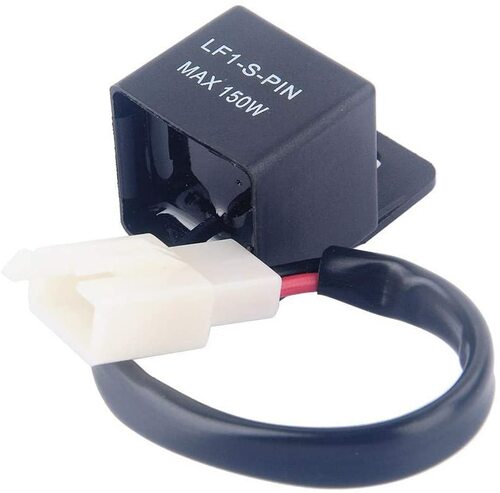
The replacement units only have two pins, unlike the OEM blinker that has three. That's OK, they work fine.