Hawkworks.net main page
Manual main index
| SERVICE INFORMATION | 15-1 |
| TROUBLESHOOTING | 15-3 |
| BATTERY | 15-4 |
| CHARGING SYSTEM | 15-7 |
| REGULATOR/RECTIFIER | 15-8 |
| ALTERNATOR | 15-10 |
After activation, the maintenance-free battery must be charged at the appropriate ampere-hour rating
for the proper length of time.
Set the Battery Amp. Hr. Selector Switch on the Christie Charger (#MC1012/2) for the size of the
battery being charged. Set the Timer to the NEW BATT position and connect the battery clamps.
When the timer reaches the “trickle” position, the charging cycle is complete.
After charging, test the condition of the new battery using the Honda Battery Tester (#BM-210) --- refer to the
Operation Manual for complete details.
Battery charging/Testing equipment
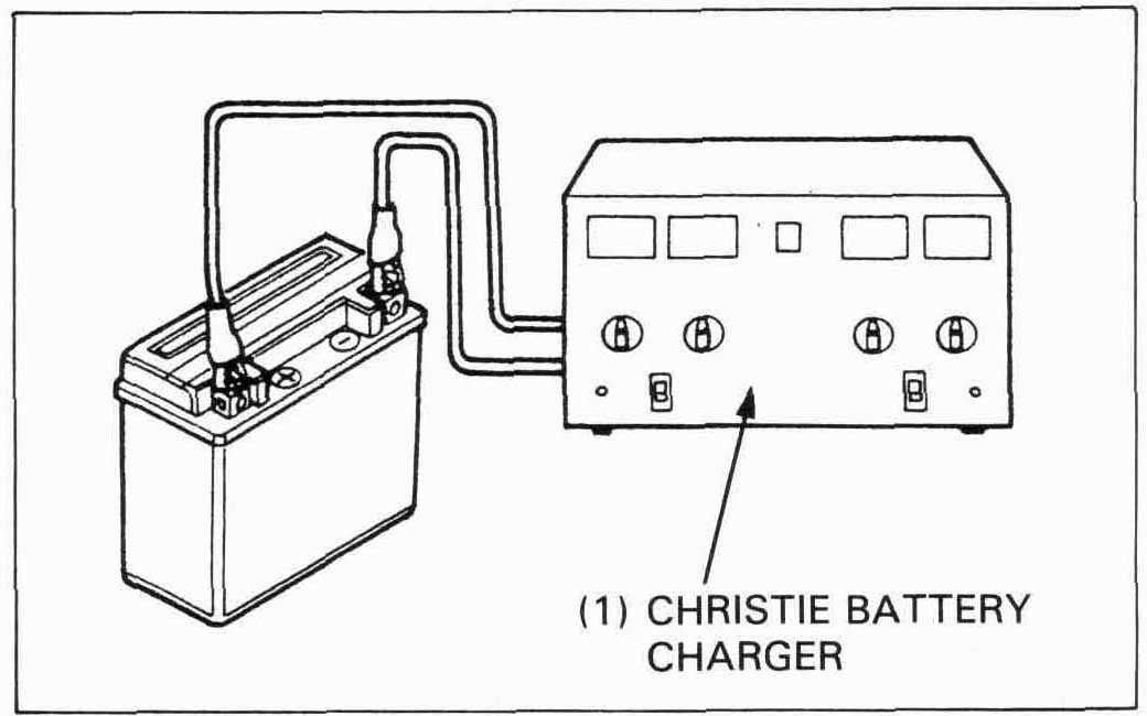
The christie Battery Charger (#MC1012/2) is a constant current (amperage) type designed to produce
current at a constant rate for the duration of the charge, even if the voltage varies.
The Honda Battery Tester (#BM-210) puts a “load” on the battery so tht the actuall battery
condition at the time of the laod can be measured.
This provides an accurate determination of the battery condition --- good (green), fair (yellow), or poor (red).
| ITEM | STANDARD | ||
| Battery | Capacity | 12 V — 8 Ah | |
| Voltage at 20°C (68°F) | Fully charged | 13.0 — 13.2 V | |
| Needs charging | 12.3 V | ||
| Leakage ampere at 20°C (68°F) | 0.1 A max. | ||
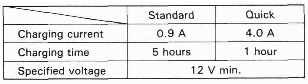
| Charging current | 0.9 amperes | ||
| Charging time | 4 Hr | ||
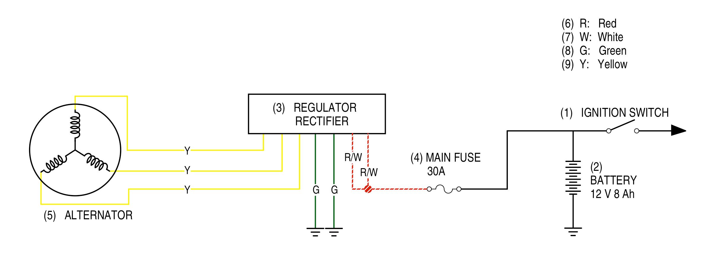
| Regululator/rectifier | Type | Three-phase/full-wave | |
| Regulated voltage/Amperage | 13.5—15.5 V/0.5 A (3,000 rpm) | ||
| Alternator | Charging coil resistance at 20°C (68°F) | 0.1 — 1.0 Ω | |
| Output | 0.24 kw/5,000 rpm | ||
| Charging start rpm | 1,200 ± 100 rpm | ||
| 07411—0020000 | (KOWA Digital type) |
| KS—AHM—32—003 | (KOWA Digital type; U.S.A. only) |
| 07308-0020001 | (SANWA Analogue type) |
| TH—5H | (KOWA Analogue type) |
| Christie battery charger | #MC 1012/2 |
| Honda battery tester | 07GMJ—0010000 |
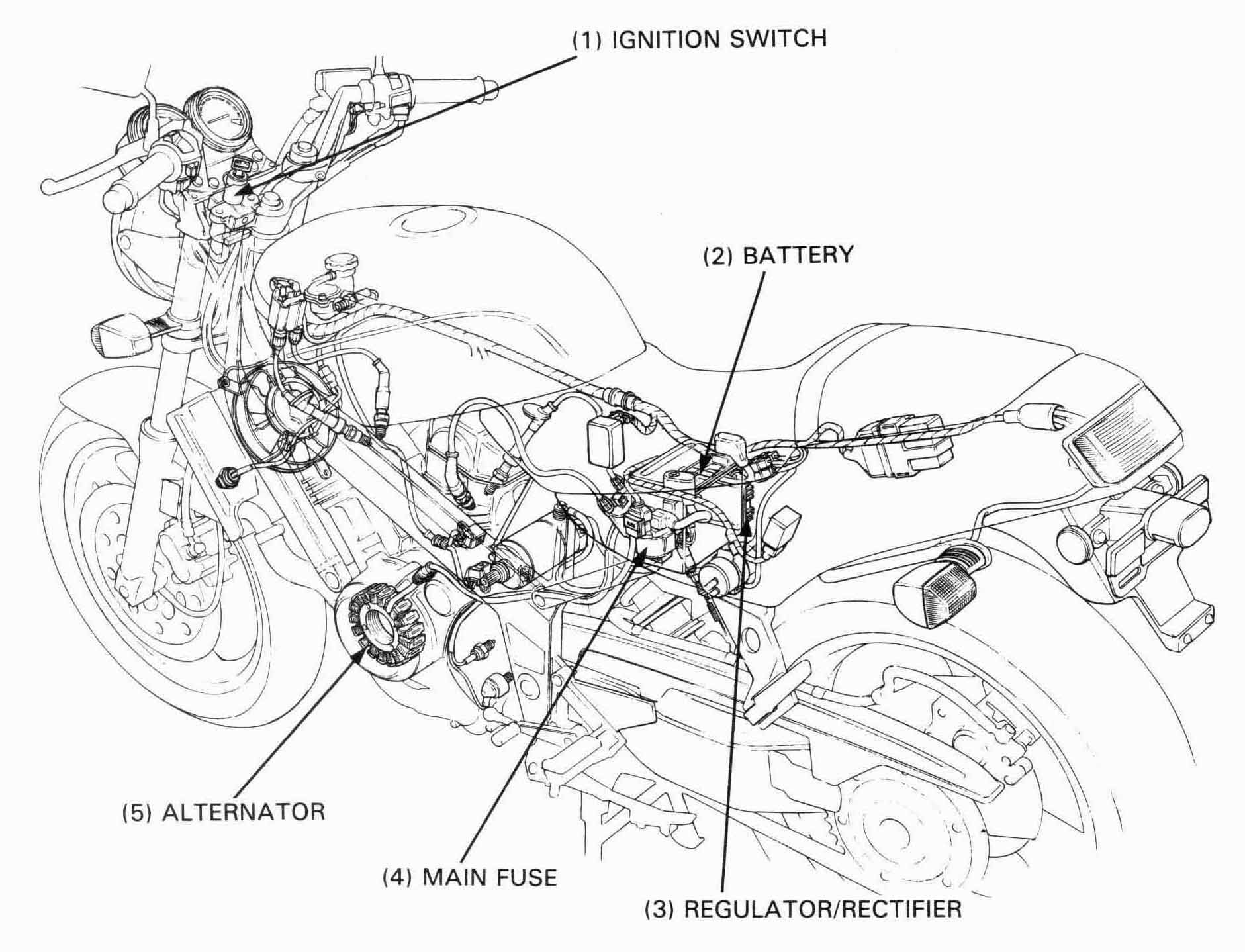
Remove the seat and turn OFF the ignition switch.
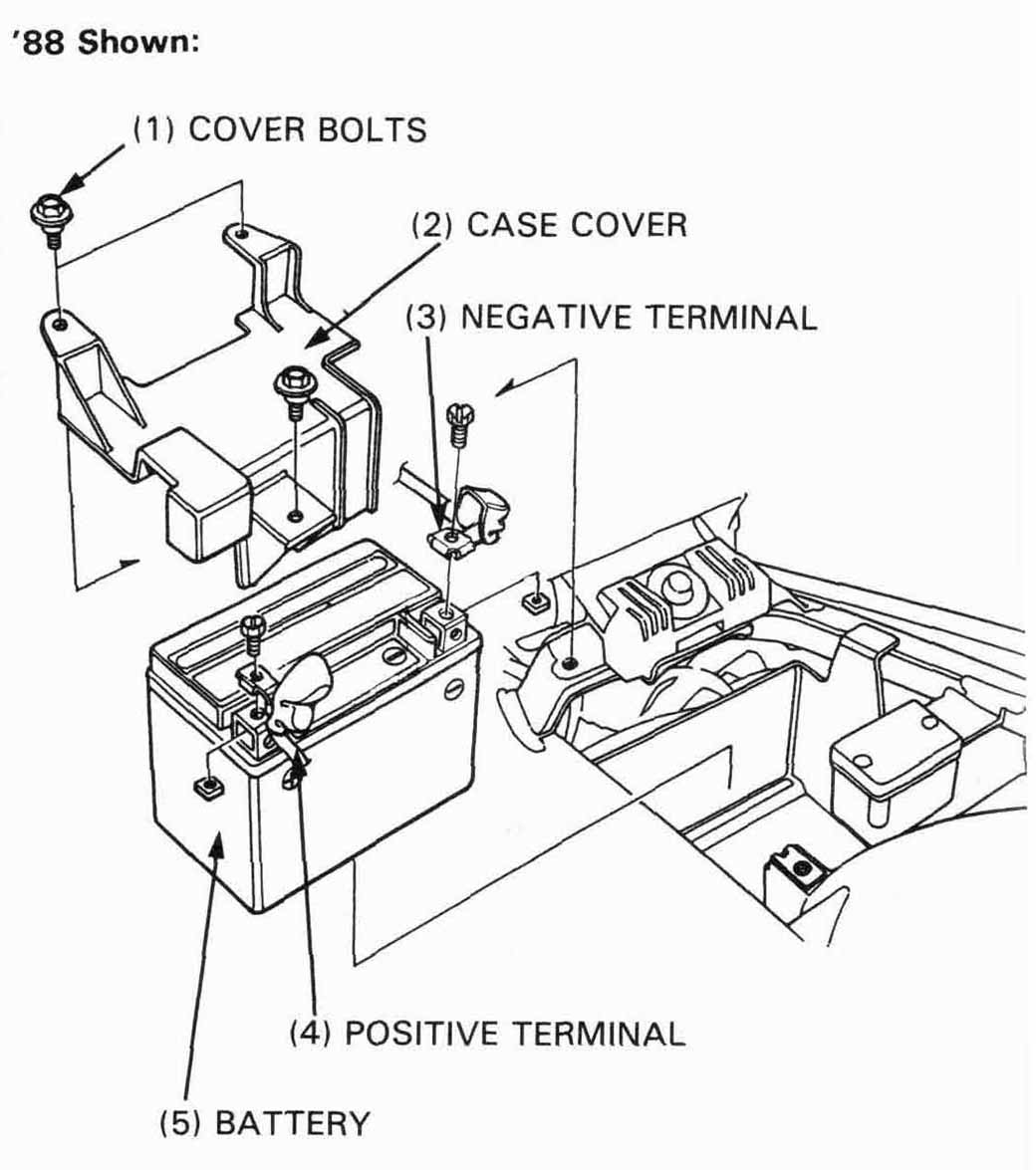
Remove the battery case cover bolts and cover
Disconnect the negative (–) termainal cable first,
then positive (+) terminal cable at the battery.
Pull the battery out of the battery holder.
Install the battery in the reverse order of removal.
After installing the battery, coat the terminals with
clean grease.

Remove the seat
Remove the battery case cover.
Measure the battery voltage.
| Voltage: | Fully charged: | 13.0—13.2 V |
| Under charged: | Below 12.3 V |
| TOOLS: | |
| Digital multimeter | 07411—0020000 (KOWA) KS—AHM—32—003 (U.S.A. only) |
| Circuit tester | TH—5H (KOWA) 07308—0020001 (SANWA) |
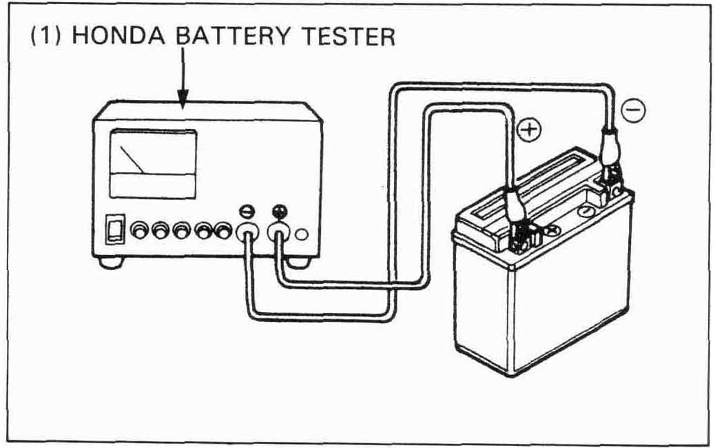
Remove the battery.
Securely connect the tester’s postitive (+)
cable first, then connect the negative (–) cable.
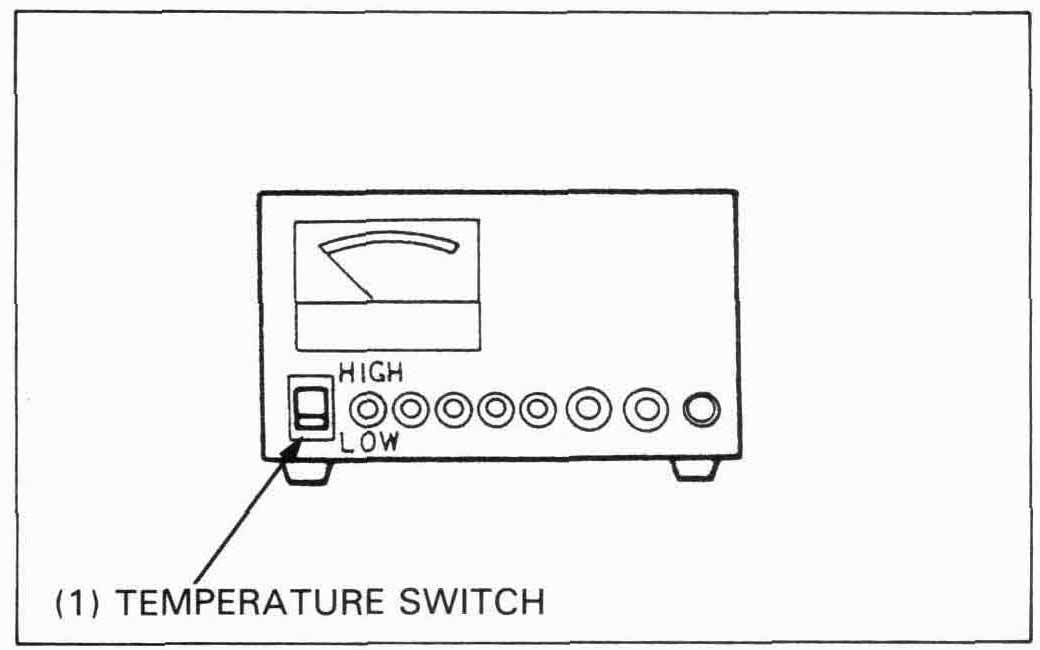
Set the temperature switch to “HIGH” or “LOW” depending on the ambient temperature.
HIGH: 15°C (60°F) or higher
LOW: 15°C (60°F) or lower
Push in the “5.5 Ah–9 Ah” test button for three seconds and read the condition of the battery on the meter.
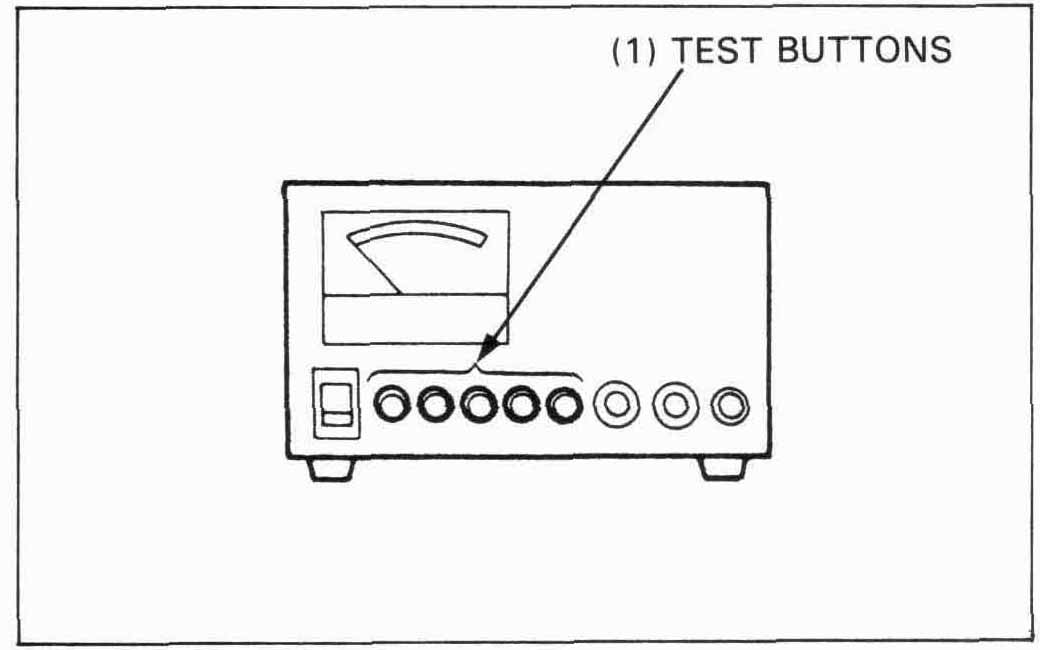

The battery is OK if the meter reading registers in the GREEN zone
If the meter reading registers in the YELLOW or RED zone, charge the battery, and re-test and judge in accordance with the chart below.
| First check: | |
| Green | : OK |
| Yellow, Red | : Charge |
| Second check: | |
| First check yellow: | |
| Green | : OK |
| Yellow | : Replace |
| First check red: | |
| Green | : OK |
| Yellow | : Recharge |
| Red: | Replace |
INFO: OEM battery is a Yuasa YTX-9BS.
Here is more information on batteries.
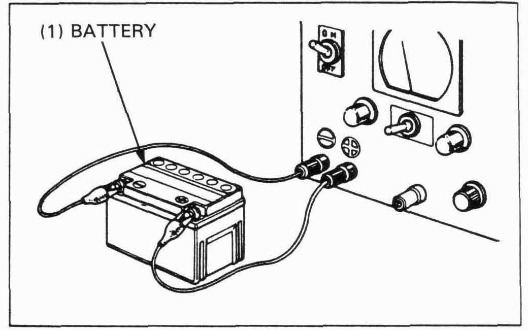
Remove the battery.
Connect the charger positive (+) cable to the battery positive
(+) terminal.
Connect the charger negative (–) cable to the battery negative
(–) terminal.
Before operating the charger:
Be sure the area around the charger is well ventilated and clear of flammable materials, heat, humidity, water and dust.
Clean the battery terminals and position the battery as far
away from the charger as the leads will permit. Do not place
the battery below the charger gases from the battery may
corrode and damage the charger.
Do not place the battery on top of the charger. Be sure the
air vents are not blocked.
Turn the Power Switch to the OFF position.
Set the Battery Amp. Hr. Selector Switch to the “5.5 to 9.0” position.
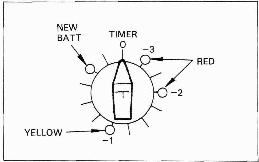
Set the Timer to the position indicated by the Honda Battery Tester: RED -3. RED -2. or YELLOW -1. If you are charging a new battery, set the switch to the NEW BATT position.
Attach the clamps to the battery terminals; RED to Positive. BLACK to Negative.
Turn the Power Switch to the ON position.
When the timer reaches the “Trickle” position, the charging cycle is complete. Turn the Power Switch OFF and disconnect the clamps.
Re-test the battery using the Honda Battery Tester and recharge if necessary using the previous steps.
Install the battery (page 15-4).
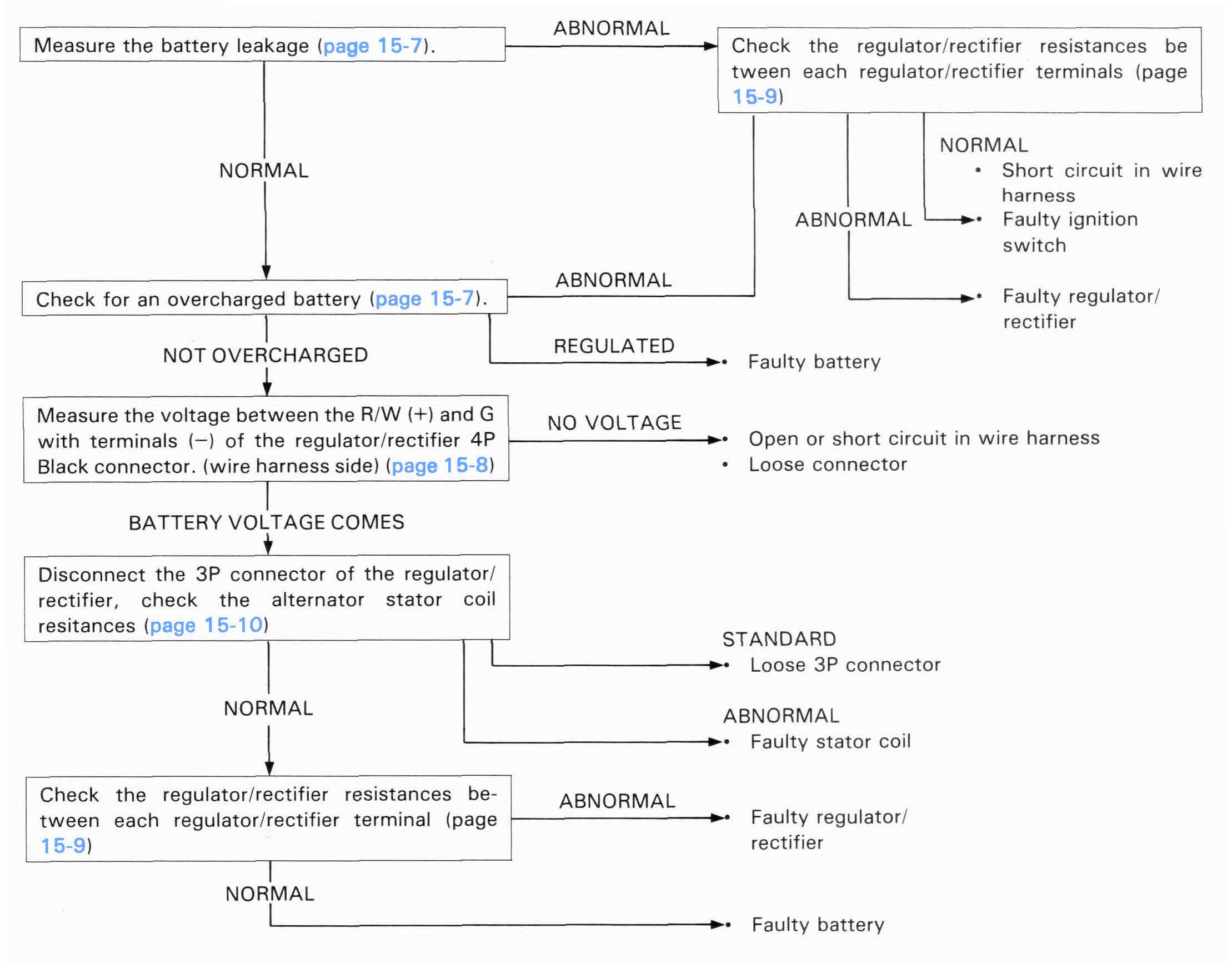
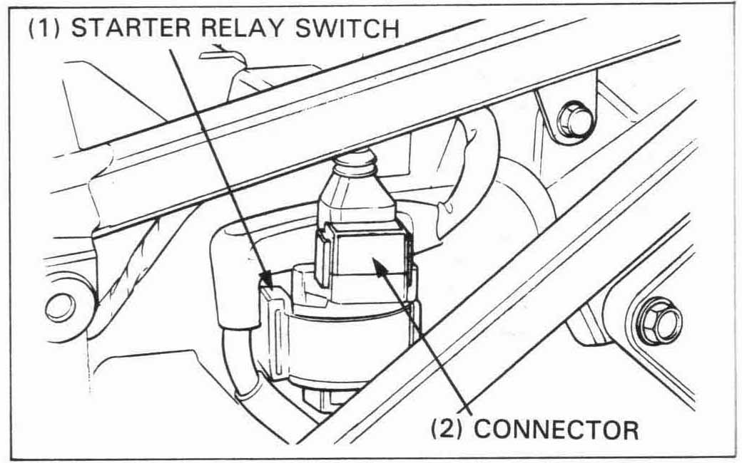
Check the battery ampere leakage before making the regulated
ampere inspection.
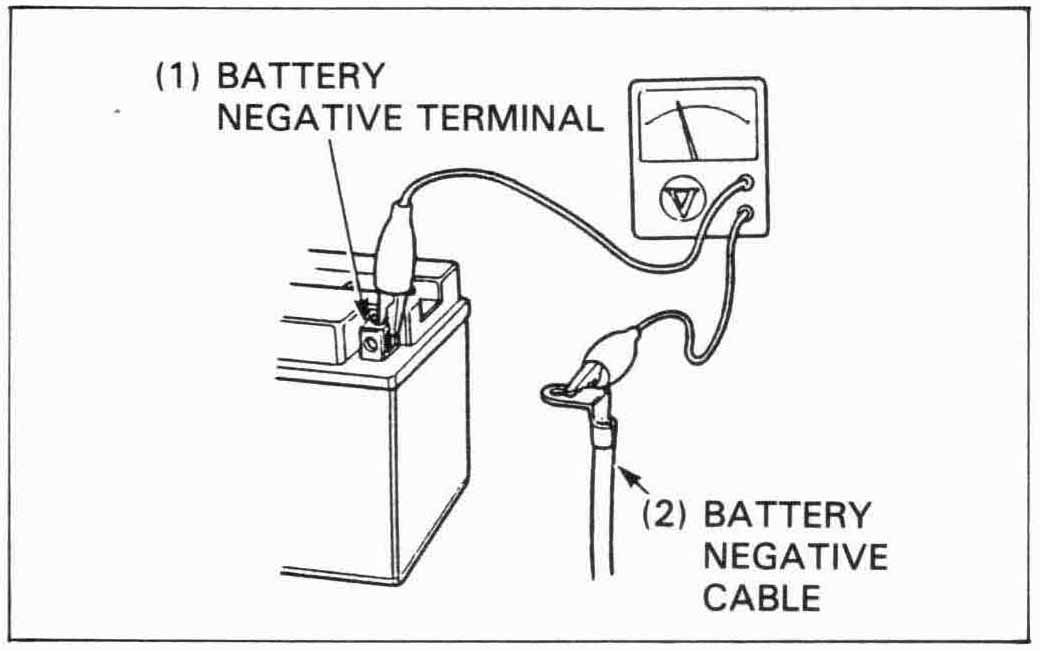
Turn the ignition switch off and disconnect the battery negative
cable from the battery.
Connect the tester between the negative cable and the negative
battery terminal.
The tester should indicate within 0.1 A with the ignition switch OFF.
LEAKAGE AMPERE: 0.1 A max (20°C (68°F)

Warm up the engine to normal operating temperature. Stop the engine, and connect the voltmeter as shown.
Remove the seat and rear cowling (page 13-25).
Disconnect the main fuse connector and remove the main
fuse.
Reconnect the connector securely.
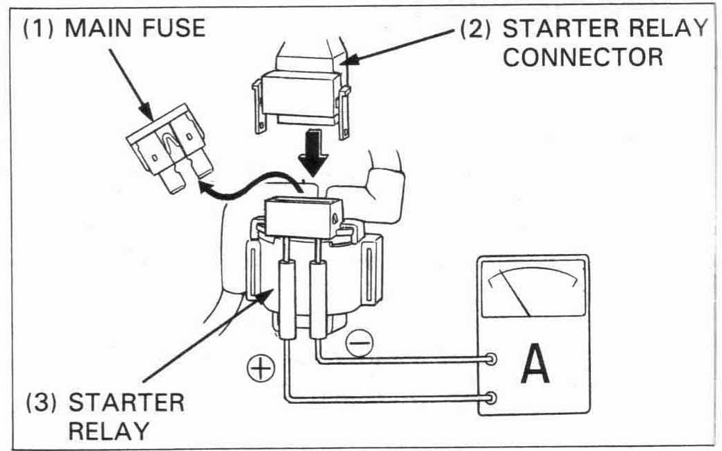
Connect the tester as shown.
Restart the engine and allow it to idle, then increase the engine
speed gradually.
The voltage and amperage should be controlled as specified
below:
STANDARD: 13.5 – 15.5 V/0.5 A (3,000 rpm) (20°C / 68°F)
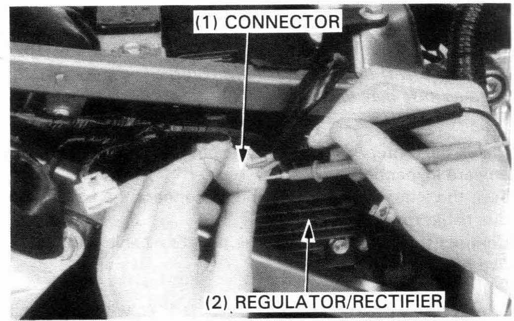
Remove the seat and rear cowling.
Disconnect the 3P (WHITE) and 4P (BLACK) regulator/rectifier
connectors.
Check the connectors for loose or corroded terminals.
If the regulated voltage reading was out of specification, check the circuits between the connector terminals (wire harness side and alternator side) following the chart on next page.
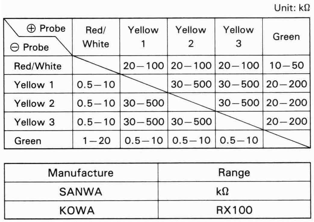
Provided the circuit on the wire harness side are normal and there are no loose connections at the connector, inspect the regulator/rectifier unit by measuring the resistance between the terminals.
| SPECIFIC MULTITESTER: | |
| — 07411—0020000 | (KOWA Digital type) |
| — KS—AHM—32—003 | (KOWA Digital type: U.S.A. only) |
| — 07308—0020001 | (SANWA Analogue type) |
| — TH—5H | (KOWA Analogue type) |
Replace the regulator/rectifier unit if the resistance value between the terminals is abnormal.
Remove the seat and rear cowling (page 13-25).
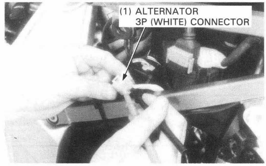
Disconnect the alternator 3P (WHITE) connector.
Measure the resistance between the yellow wire terminals and check for no continuity between each terminal and ground.
STANDARD: 0.1-1.0 Ω (20°C/68°F)