Hawkworks.net main page
Manual main index
| SERVICE INFORMATION | 8-1 |
| LEFT CRANKCASE COVER REMOVAL | 8-2 |
| FLYWHEEL REMOVAL | 8-3 |
| STARTER CLUTCH | 8-4 |
| FLYWHEEL INSTALLATION | 8-5 |
| LEFT CRANKCASE COVER INSTALLATION | 8-6 |
mm (in)
| ITEM | STANDARD | SERVICE LIMIT |
|---|---|---|
| Starter driven gear O.D. | 57.747-57.768 (2.2736—2.2743) | 57.60 (2.268) |
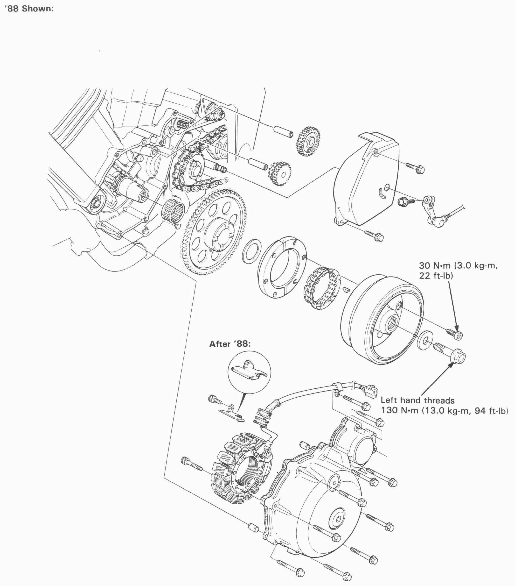
| Flywheel bolt | 130 N•m (13.0 kg-m, 94 ft-lb) Left-hand thread |
| Starter clutch Torx bolts | 30 N•m (3.0 kg-m, 22 ft-lb) Apply locking agent to the threads |
| Common | ||
| rotor puller | 07733—0020001 or 07933—3290001 | |
| Flywheel holder | 07725—0040000 | Equivalent commerically avalable in U.S.A. |
| T-40 Torx Bit | 07703—0010100 |

Disconnect the alternator 3P connector (WHITE)
Remove the gearshift arm pinch bolt and shiftarm from the spindle.
Remove the drive sprocket cover.
Place a container under the left crankcase cover to catch the engine oil.
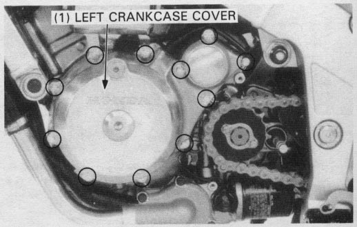
Remove the eleven left crankcase cover bolts and the cover.

Remove the dowel pins and gasket.

Remove the wire clamp bolts and the clamps.
Remove the stator mounting bolts and stator.
Position the new stator and the grommets in the cover.
Apply a locking agent to the threads of the stator mounting bolts.
Tighten the stator mounting bolts and the clamp bolts.
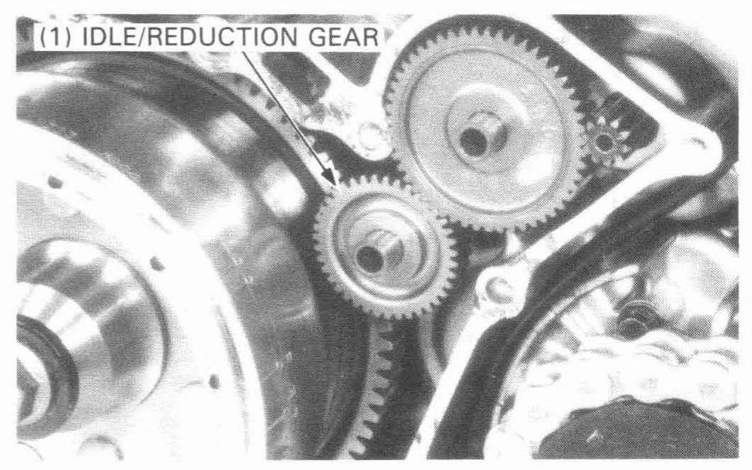
Remove the starter idle/reduction gear by removing the shaft.
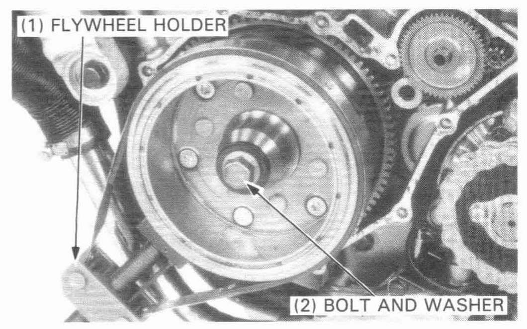
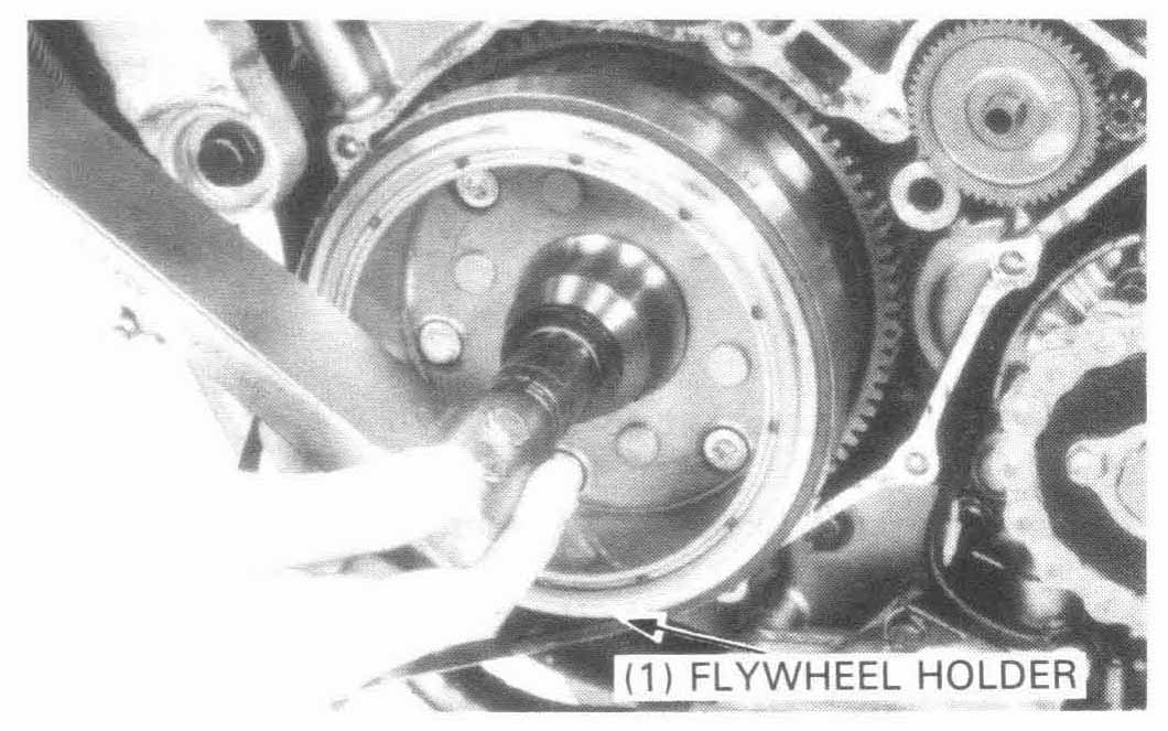
Hold the flywheel with the flywheel holder and remove the flywheel bolt and washer.
| TOOL: | |
| Flywheel holder | 07725—0040000 Equivalent commercially available in U.S.A. |
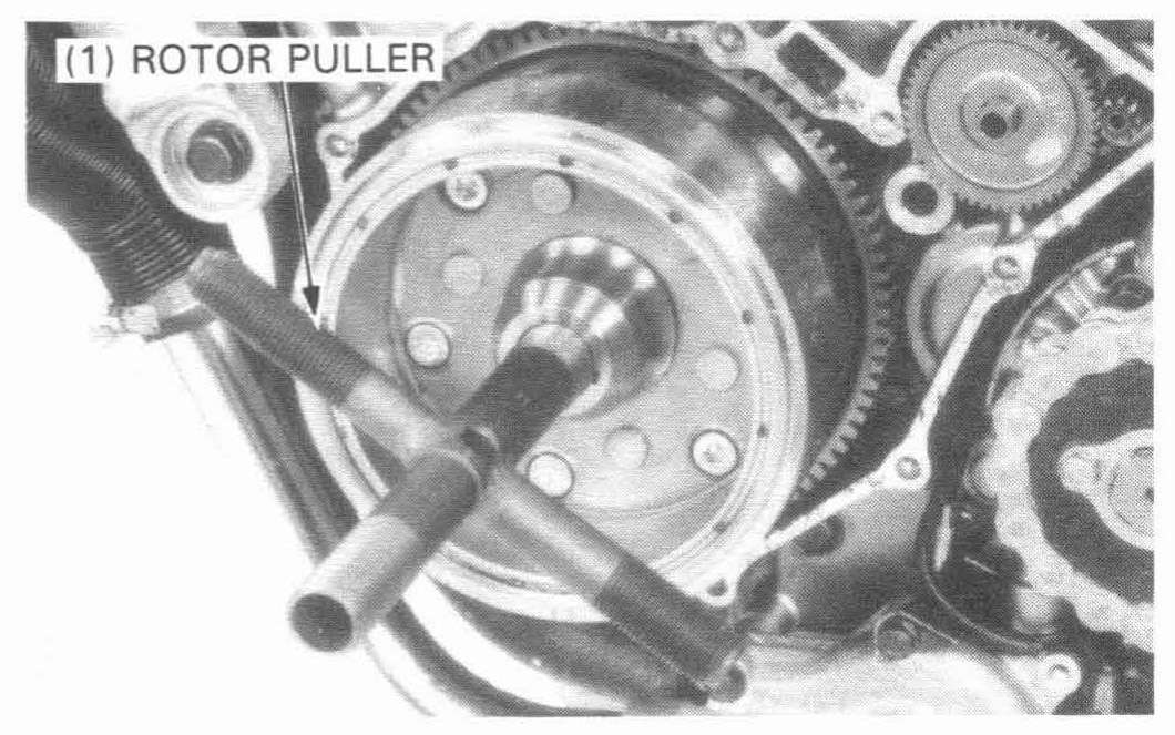
Remove the flywheel with the rotor puller.
| TOOL: | |
| Rotor puller | 07733—0020001 or 07933—3290001 |
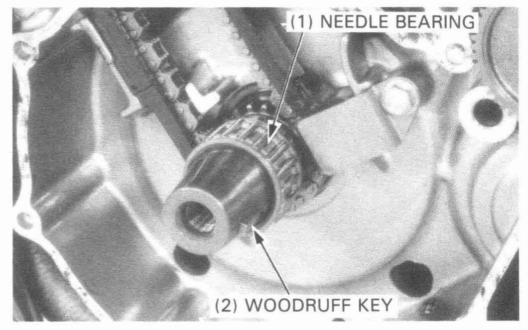
Remove the needle bearing from the crankshaft, then remove the woodruff key.
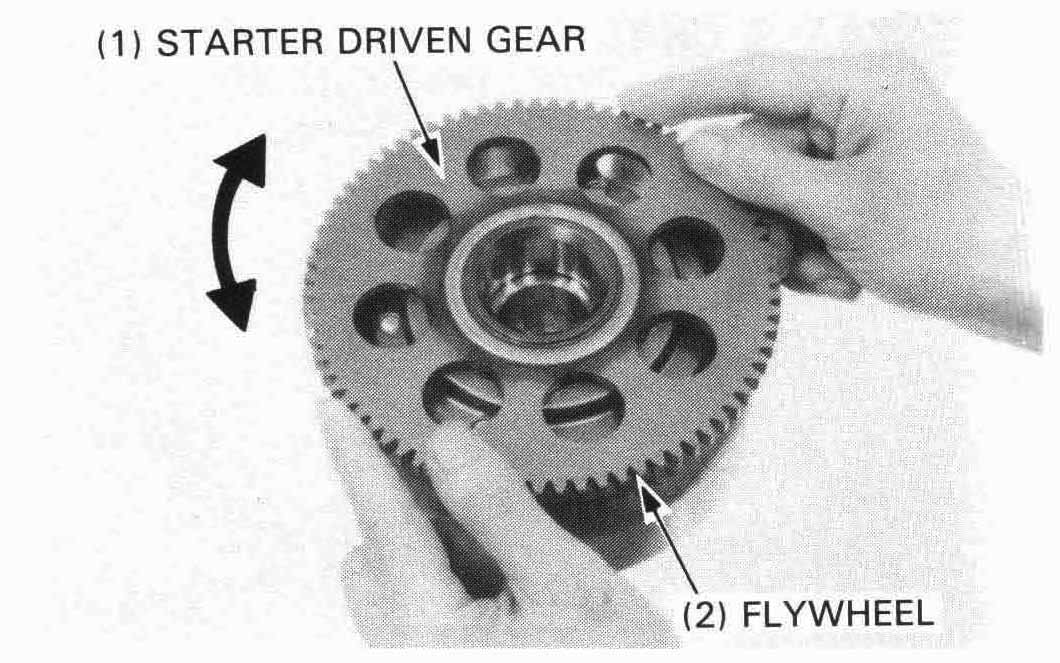
Reinstall th starter driven gear into the flywheel.
Inspect the starter clutch by turning the starter driven gear. The gear should turn counterclockwise freely and should not turn clockwise: if it turns incorrectly, replace the starter clutch.
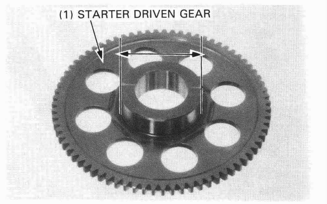
Measure the O.D. of the starter driven gear.
SERVICE LIMIT: 57.60 mm (2.268 in)
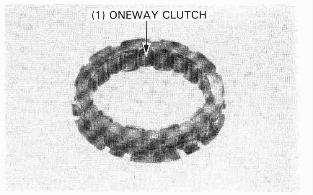
Inspect the oneway clutch for wear or damage and replace if necessary.
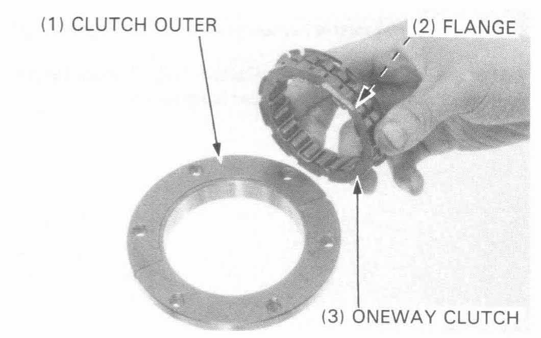
Install the oneway clutch into the outer with the flange side facing inside.
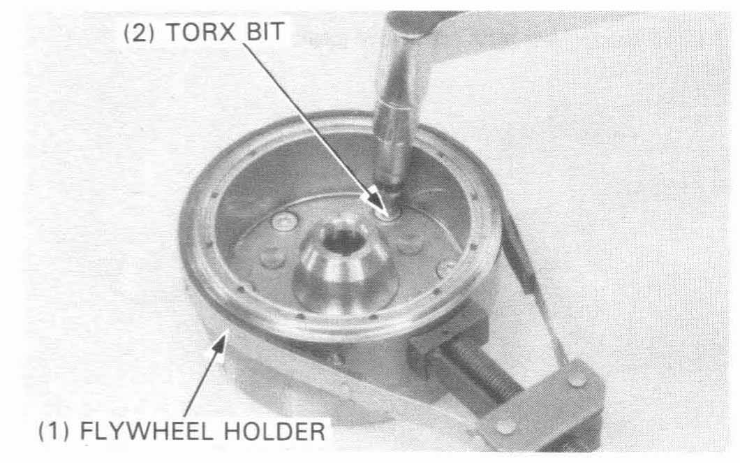
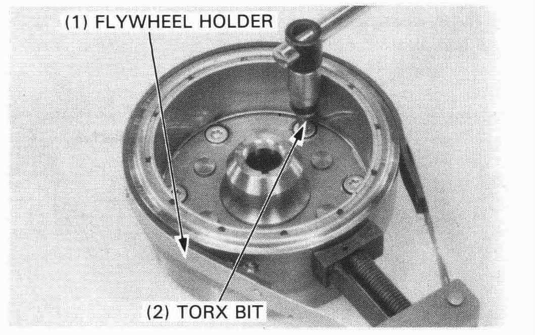
Hold the flywheel with the flywheel holder. Apply locking agent to the torx bolt threads and tighten the bolts.
TORQUE: 30 N•m (3.0 kg-m, 22 ft-lb)
| TOOLS: | ||
| Flywheel holder | 07725—0040000 | Equivalent commercially available in U.S.A. |
| T-40 Torx bit | 07703—0010100 |
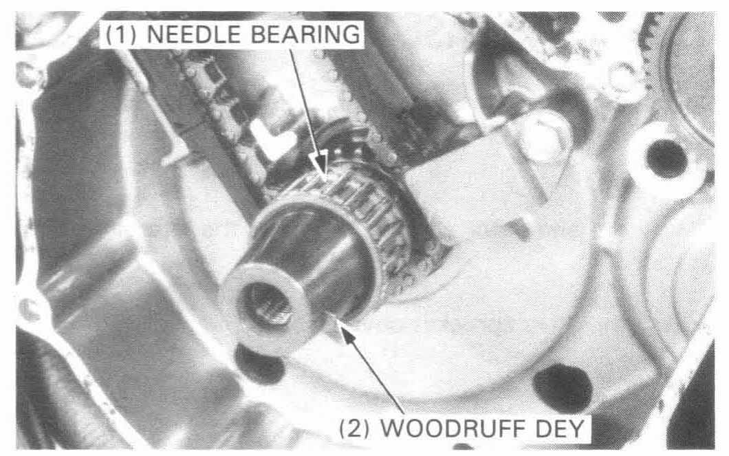
Clean the crankshaft and install the woodruff key.
Install the needle bearing into the crankshaft.
Install the driven gear and flywheel, aligning the woodruff key on the crankshaft with the flywheel keyway.
Hold the flywheel with the flywheel holder, install the washer and flywheel bolt and tighten the bolt.
TORQUE: 130 N•m (13.0 kg-m, 94 ft-lb)
| TOOL: | |
| Flywheel holder | 07725—0040000 Equivalent commercially available in U.S.A. |

Install the starter idle/reduction gear with the longer shaft.
Install the starter drive gear with the “OUT” mark facing out and the shorter shaft, if the gear is removed.
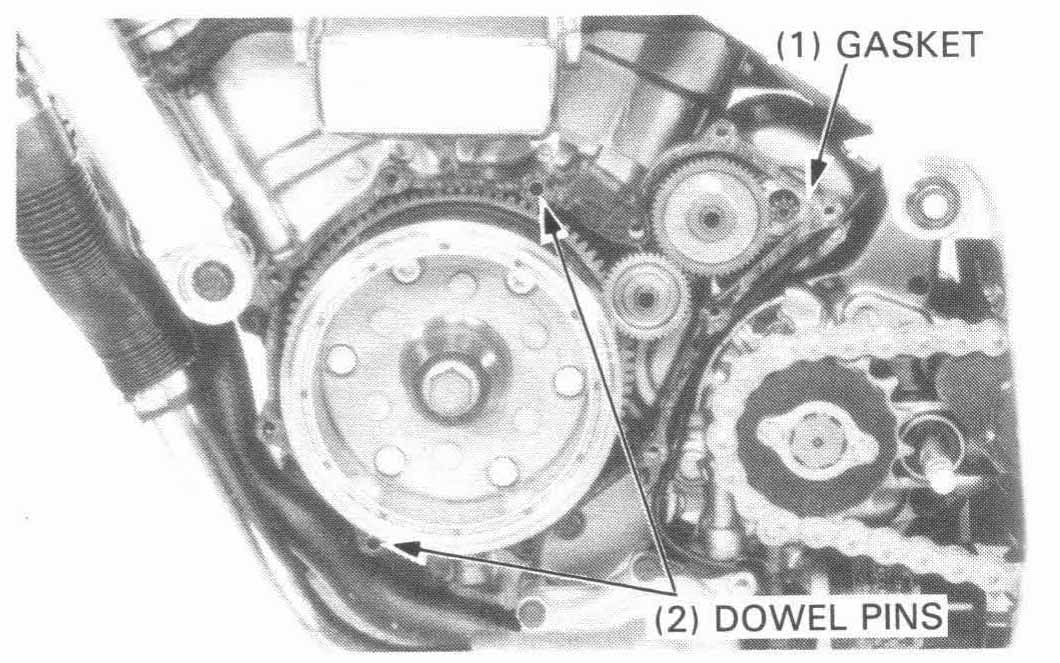
Install the dowel pins and new gasket
Info: Gasket part number is 11395-MR1-000, about $10
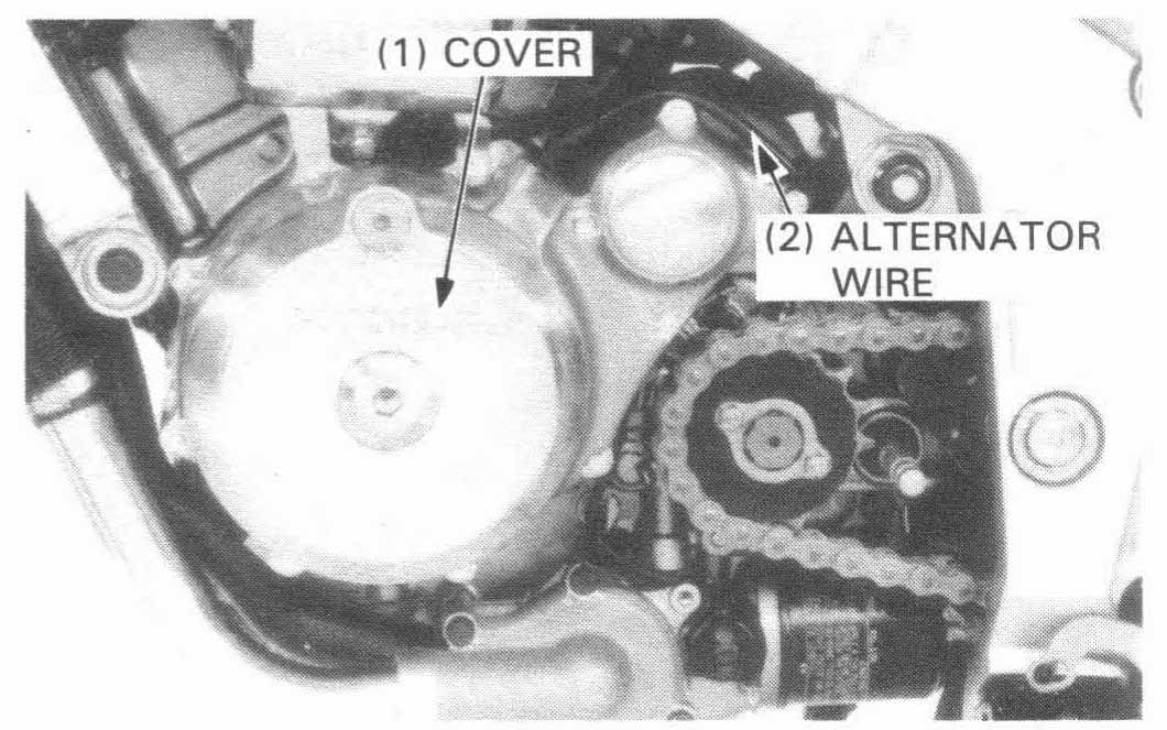
Install the left crankcase cover and tighten the cover bolts with the neutral and oil pressure switch wire harness clamps as shown.
Route the alternator wire and connect the alternator 3P connector
Install the drive sprocket cover.
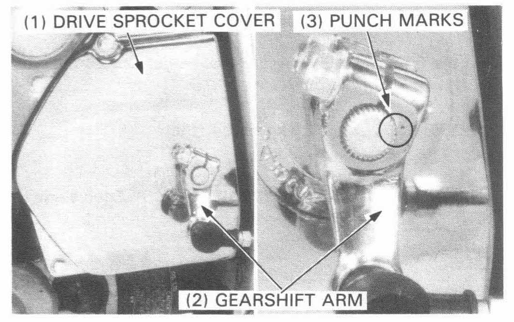
Install the gearshift arm into the spindle by aligning the punch mark on the arm with the punch mark on the spindle
Tighten the gearshift arm pinch bolt.
TORQUE: 12 N•m (1.2 kg-m, 9 ft-lb)
Install the drive sprocket cover.
Check the engine oil level and add the oil if necessary.