
really big verson
Hawkworks.net main page
Manual main index
| SERVICE INFORMATION | 9-1 |
| TROUBLESHOOTING | 9-2 |
| CYLINDER HEAD COVER REMOVAL | 9-3 |
| CAMSHAFT REMOVAL | 9-3 |
| CYLINDER HEADS | 9-7 |
| VALVE GUIDE REPLACEMENT | 9-11 |
| VALVE SEAT INSPECTION/REFACING | 9-12 |
| CYLINDER HEAD ASSEMBLY | 9-14 |
| CYLINDER HEAD INSTALLATION | 9-15 |
| CAMSHAFT INSTALLATION | 9-17 |
| CYLINDER HEAD COVER INSTALLATION | 9-20 |
Unit: mm (in)
| ITEM | STANDARD | Service limit | |||
|---|---|---|---|---|---|
| Compression pressure | 1,324 ± 196 kPa (13.5 ± 2.0kg/cm², 192 ± 28 psi) | --- | |||
| Camshaft | Cam lobe height | IN | 38.189 (1.5035) | 38.17 (1.503) | |
| EX | 38.213 (1.5044) | 38.19 (1.504) | |||
| Journal O.D. | 21.959-21.980 (0.8645-0.8654) | 21.95 (0.864) | |||
| Runout | 0.030 (0.0012) | 0.05 (0.002) | |||
| Oil Clearance | 0.040-0.093 (0.0015-0.0037) | 0.11 (0.004) | |||
| Rocker arm | Rocker arm I.D. | IN/EX | 12.000-12.018 (0.4724-0.4731) | 12.03 (0.474) | |
| Rocker arm shaft O.D. | IN/EX | 11.966-11.984 (0.4711-0.4718) | 11.96 (0.471) | ||
| Valve and valve guide | Valve stem O.D. | IN | 5.475-5.490 (0.2156-0.2161) | 5.47 (0.215) | |
| EX | 6.555-6.570 (0.2580-0.2587) | 6.55 (0.258) | |||
| Valve guide I.D. | IN | 5.500-5.512 (0.2165-0.2170) | 5.53 (0.218) | ||
| EX | 6.600-6.615 (0.2598-0.2604) | 6.66 (0.262) | |||
| Stem-to-guide clearance | IN | 0.010-0.037 (0.0004-0.0015) | 0.07 (0.003) | ||
| EX | 0.030-0.060 (0.0014-0.0024) | 0.11 (0.004) | |||
| Valve seat width | 0.9-1.1 (0.035-0.043) | 1.5 (0.06) | |||
| Valve guide pro- jection height | IN | 19.4-19.6 (0.76-0.77) | --- | ||
| EX | 17.9-18.1 (0.70-0.71) | --- | |||
| Valve spring | Free length | OUTER | IN | 42.14 (1.659) | 40.58 (1.598) |
| EX | 42.83 (1.686) | 41.25 (1.624) | |||
| INNER | IN | 38.11 (1.500) | 36.47 (1.436) | ||
| EX | 38.81 (1.765) | 37.51 (1.477) | |||
| Cylinder head warpage | --- | 0.10 (0.004) | |||
| Cylinder head cover bolt | 10 N•m (1.0 kg-m, 7.2 ft-lb) | |
| Camshaft holder | 8 mm bolt | 23 N•m (2.3 kg-m, 17 ft-lb) |
| 8 mm nut | 23 N•m (2.3 kg-m, 17 ft-lb) | |
| 6 mm bolt | 10 N•m (1.0 kg-m, 7.2 ft-lb) | |
| Cylinder head | 10 mm nut | 48 N•m (4.8 kg-m, 35 ft-lb) |
| 8 mm bolt | 23 N•m (2.3 kg-m, 17 ft-lb) | |
| 8 mm nut | 23 N•m (2.3 kg-m, 17 ft-lb) | |
| 6 mm bolt | 10 N•m (1.0 kg-m, 7.2 ft-lb) | |
| Camshaft sprocket bolt | 10 N•m (1.0 kg-m, 7.2 ft-lb) | |
| Cam chain tensioner bolt | 10 N•m (1.0 kg-m, 7.2 ft-lb) | |
| Oil pass pipe | 7 mm bolt | 10 N•m (1.0 kg-m, 7.2 ft-lb) |
| 8 mm bolt | 23 N•m (2.3 kg-m, 17 ft-lb) | |
| Special | |
| Valve guide reamer (IN) | 07984—2000001 or 07984—200000B (U.S.A. only) |
| Valve guide reamer (EX) | 07984—ZE20001 or 07984—ZE2000B (U.S.A. only) |
| Valve guide driver attachment (IN) | 07943—MF50100 |
| Valve guide driver attachment (EX) | 07943—MF50200 |
| Common | |
| Valve guide driver, 5.5 mm (IN) | 07742—0010100 |
| Valve guide driver, 6.6 mm (EX) | 07742—0010200 or 07942—6570100 U.S.A. only |
| Valve spring compressor | 07757—0010000 or 07957—3290001 |
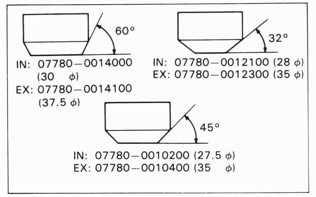
| Valve seat cutter | (Not available in U.S.A) | |
| Cutter holder | IN 5.5 mm | 07781—0010101 |
| EX 6.6 mm | 07781—0010201 | |
| Flat cutter | IN 28 mm (32°) | 07780—0012100 |
| EX 35 mm (32°) | 07780—0012300 | |
| Interior cutter | IN 30 mm (60°) | 07780—0014000 |
| EX 37.5 mm (60°) | 07780—0014100 | |
| Seat cutter | IN 27.5 mm (45°) | 07780—0010200 |
| EX 35 mm (45°) | 07780—0010400 | |
Uneven or low compression
Remove the following parts:
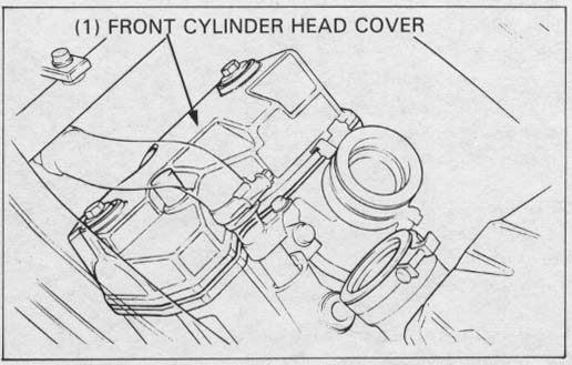
Disconnect the spark plug caps.
Remove the cylinder head cover bolts and cover.
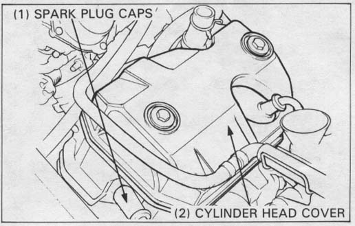
Disconnect the spark plug caps.
Remove the cylinder head cover bolts and cover.
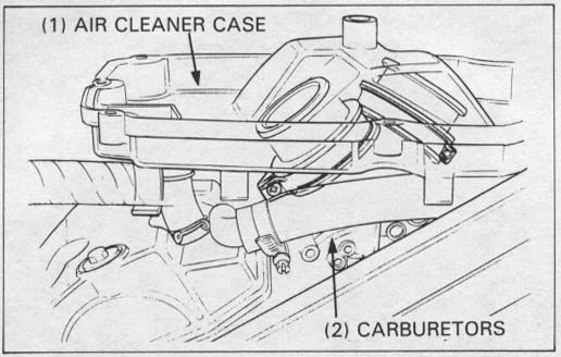
Remove the cylinder head covers (page 9-3)
and carburetors (page 4-5).
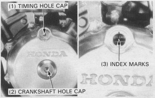
Remove the timing hole cap and crankshaft hole cap from the left
crankcase cover.
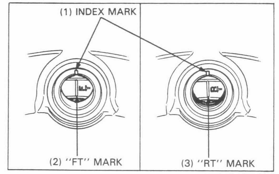
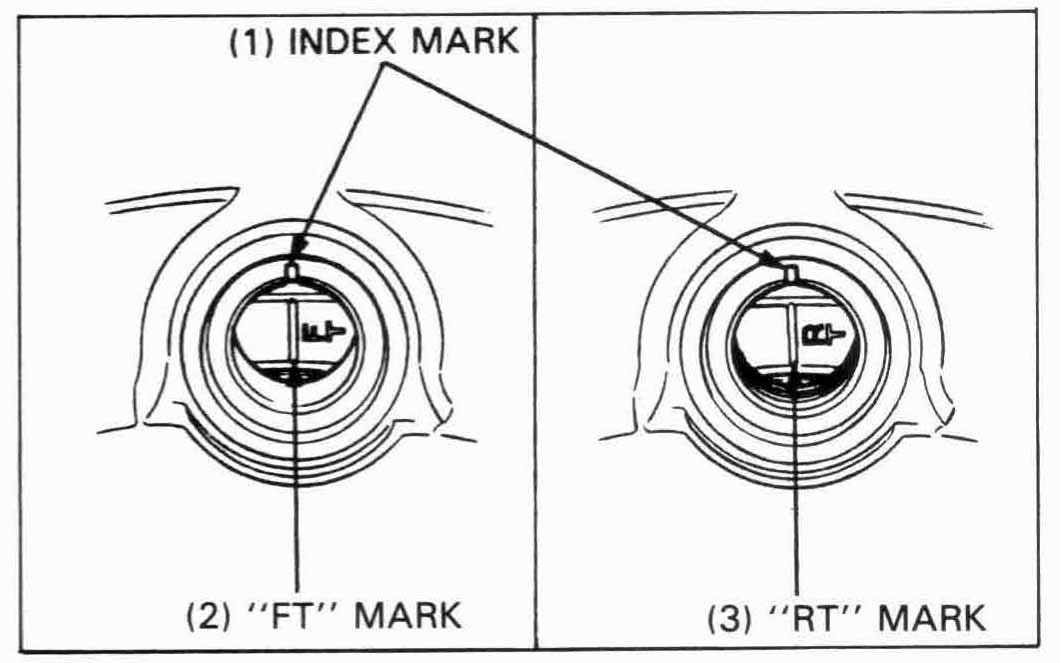
Align the FT mark (rear: RT mark) on the flywheel with the
index mark on the left crankcase cover timing hole by turning
the crankshaft counterclockwise.
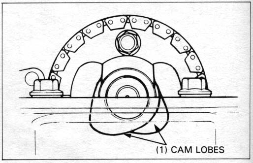
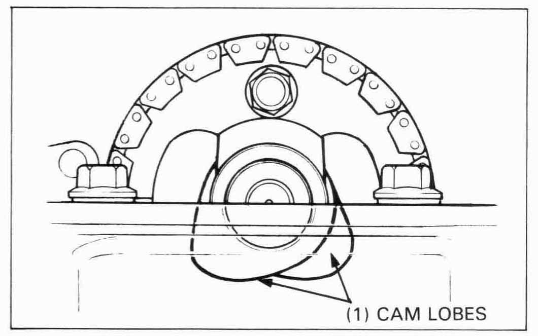
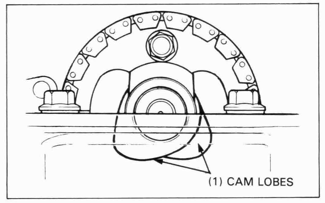
Make sure the piston is at TDC (TOP DEAD CENTER) on the compression stroke so the cam lobes are all facing down.
If the cam lobe is facing up at TDC, turn the crankshaft 360° couterclockwise, and re-align the mark and notch.
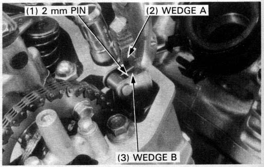
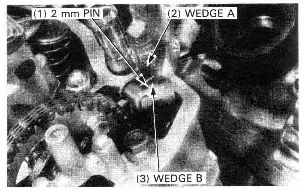
Pull wedge A straight up while holding wedge B down.
Secure wedge A with a 2 mm pin as shown.
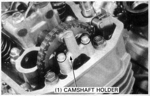
Remove the camshaft holder on the cam sprocket side by removing the two mounting bolts.
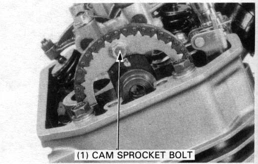
Remove the cam sprocket bolt, rotate the crankshaft counterclockwise one turn (360°) and remove the other cam sprocket bolt.
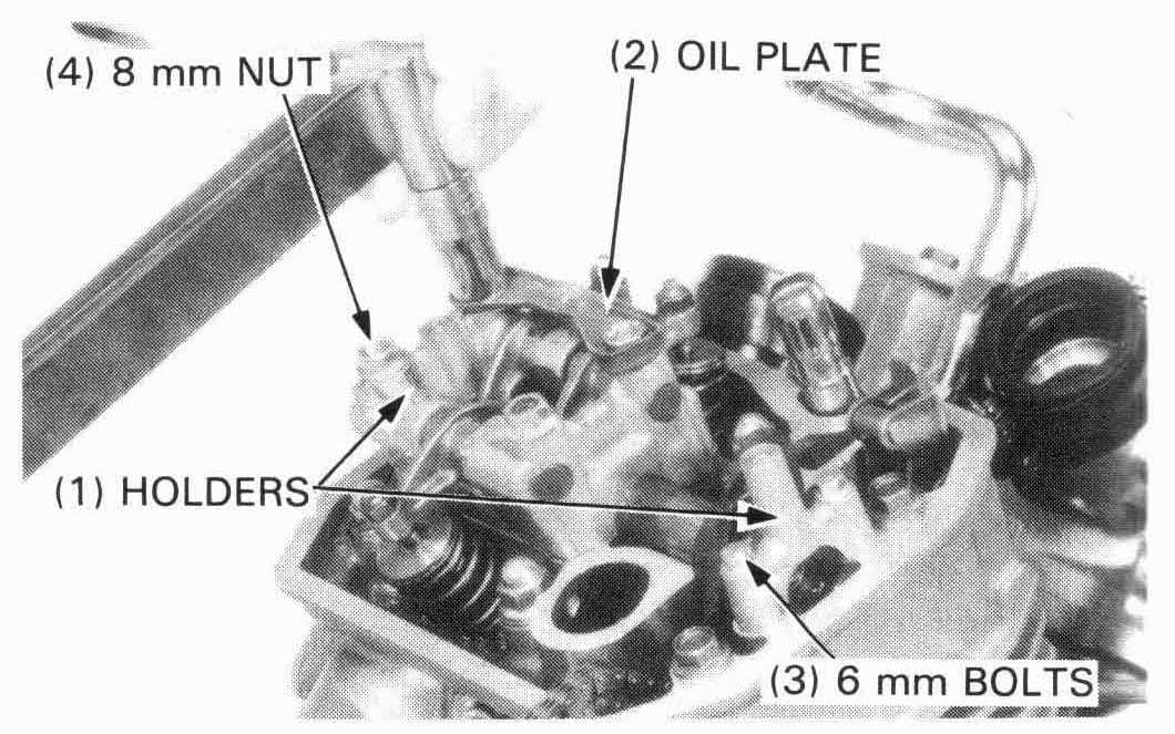
Remove the three camshaft holder mounting bolts and the nut, the oil plate and the holder.
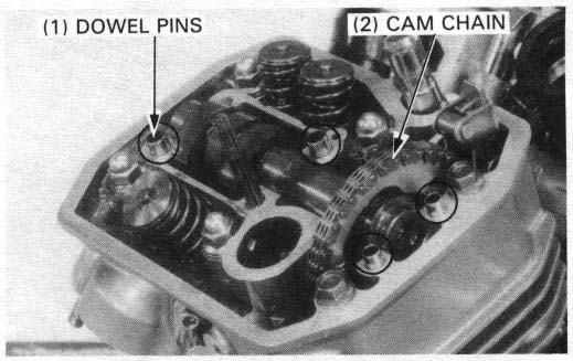
Remove the dowel pins.
Hang the cam chain on the camshaft behind the camshaft
flange and remove the cam sprocket while lifting the camshaft
out.
Attach a piece of wire to the cam chain to prevent it from being dropped into the crankcase.

Inspect the camshaft holder and cylinder head journal surfaces for scoring or evidence of insufficient lubrication.
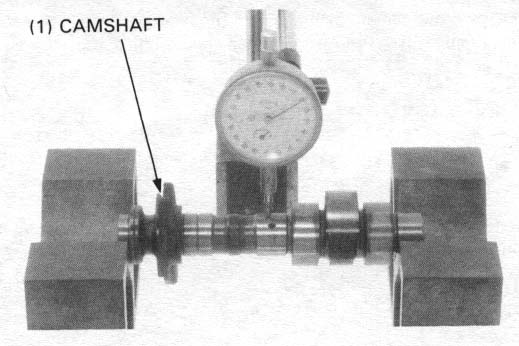
Camshaft runout
Support both ends of the camshaft with V-blocks and check the camshaft runout with a dial indicator.
SERVICE LIMIT: 0.05 mm (0.002 in)
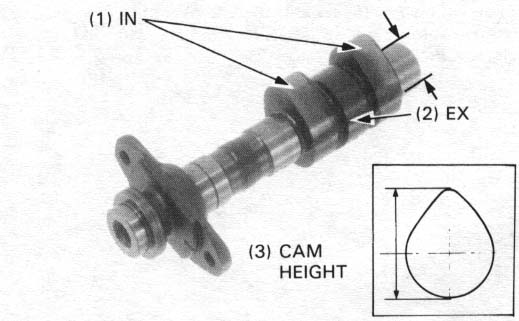
Using a micrometer, measure the height of each cam lobe.
SERVICE LIMIT:
IN: 38.17 mm (1.503 in)
EX: 38.19 mm (1.504 in)
Check the camshaft journals for wear or damage.
Measure the O.D. of each journal.
SERVICE LIMIT: 21.95 mm (0.864 in)
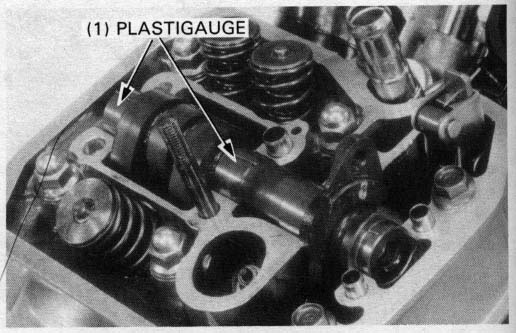
Camshaft bearing oil clearance
Wipe any oil from the journals. Lay a strip of plastigauge
lengthwise on top of each camshaft journal.
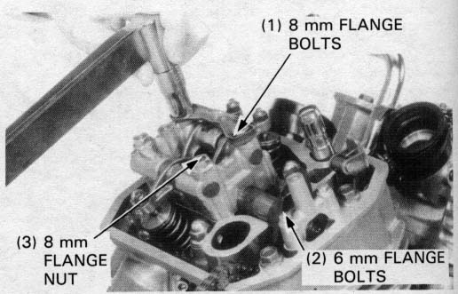
Install the camshaft holders and tighten the mounting bolts in a crisscross pattern in 2 or 3 steps.
TORQUE:
6 mm flange bolt: 12 N•m (1.2 kg-m, 9 ft-lb)
8 mm flange bolt: 23 N•m (2.3 kg-m, 17 ftlb)
8 mm flange nut: 23 N•m (2.3 kg-m, 17 ft-lb)
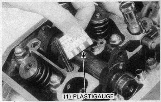
Remove the camshaft holder and measure the width of each plastigauge. The widest thickness determines the oil clearance.
SERVICE LIMIT: 0.11 mm (0.004 in)
When the service limit is exceeded, replace the camshaft and recheck the oil clearance.
Replace the cylinder head and camshaft holder if the clearance still exceeds the service limit.
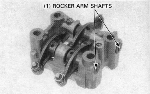
Camshaft holder/Rocker arm shaft/Rocker arm
Remove the rocker arm shafts by tapping the holder with a
soft hammer.
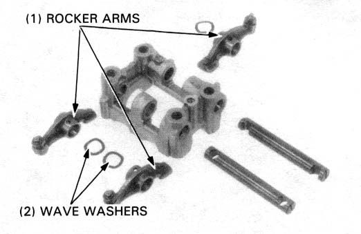
Remove the rocker arms and wave washers from the shafts.
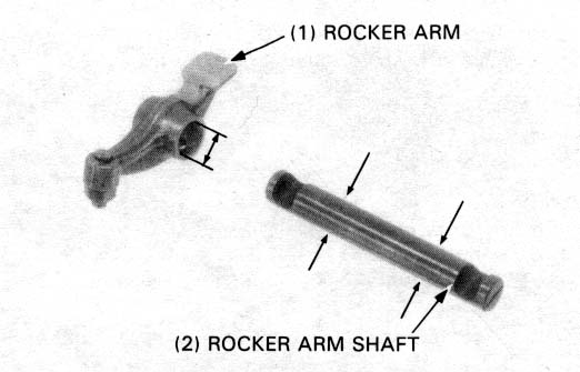
Inspect the rocker arm shafts and rocker arms for wear or damage.
Check the rocker arms for clogged oil holes.
Measure the O.D. of each rocker arm shaft.
SERVICE LIMIT:
IN/EX: 11.96 mm (0.471 in)
Measure the l.D. of each rocker arm.
SERVICE LIMIT: 12.03 mm (0.474 in)
Drain the coolant (page 5-3) and remove the following:
Disconnect the clutch cable from the clutch lifter arm by removing
the clutch cable holder bolt.
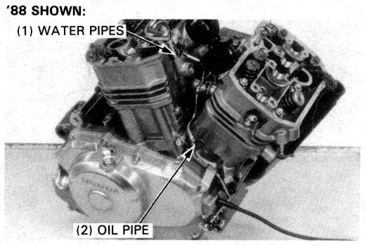
Remove the oil pipe from the engine.
Remove the water pipes.
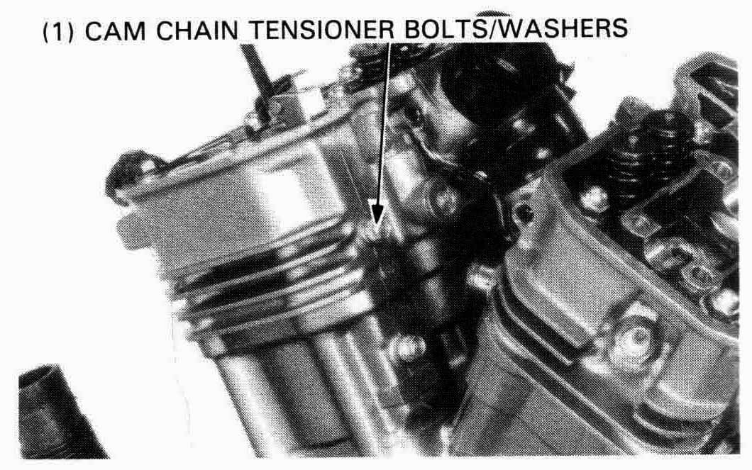
Remove the cam chain tensioner mounting bolts and washers from the cylinder head and cylinder.
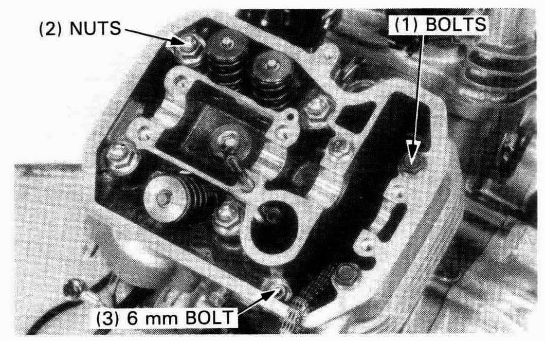
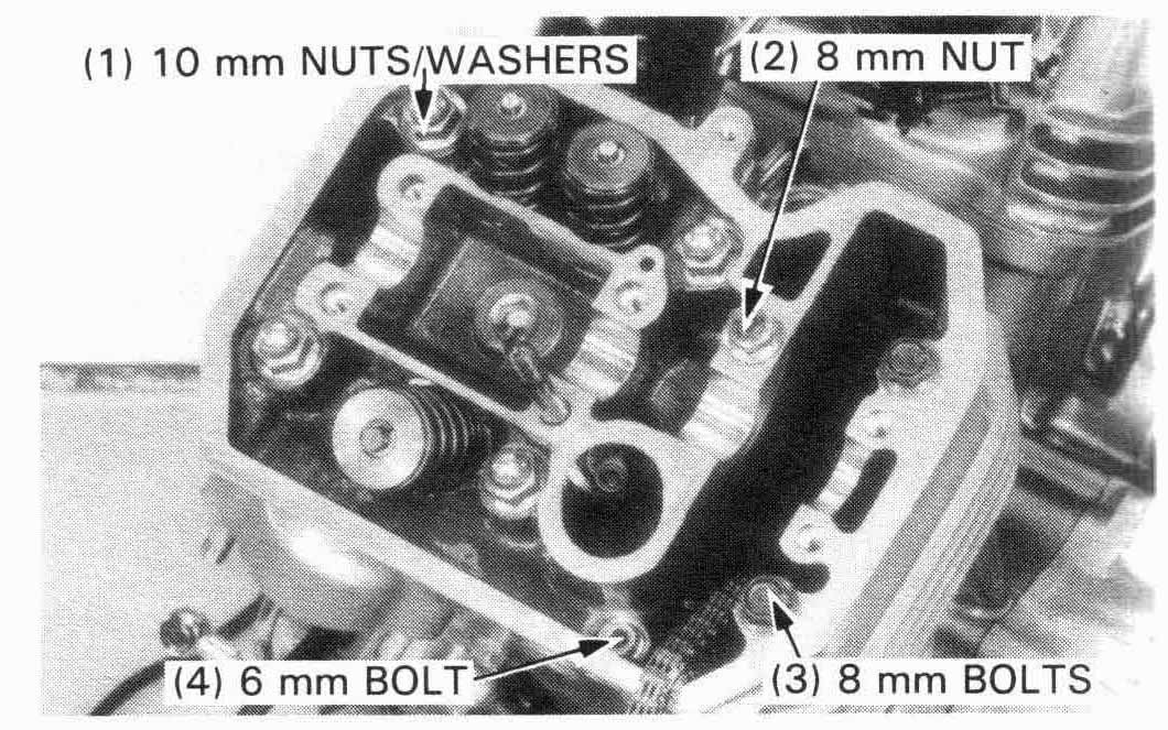
Loosen the 6 mm bolt, 8 mm bolts, 8 mm nut and 10 mm
nuts/washers in a criss-cross pattern in 2 or three steps.
Remove the bolts and nuts.
FRONT:
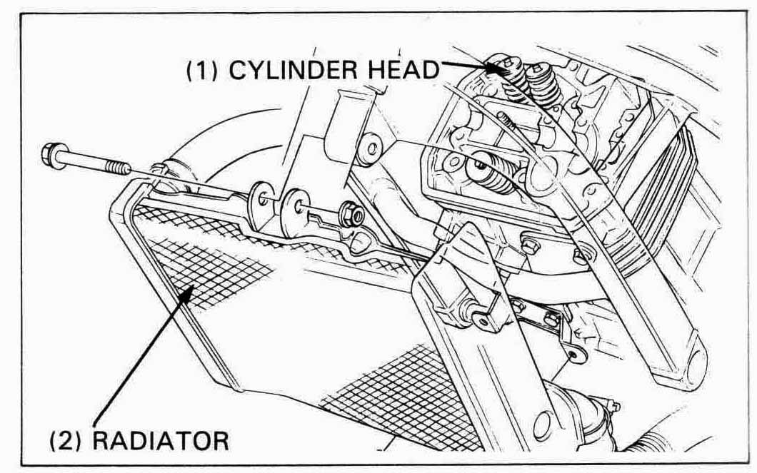
Remove the radiator mounting bolts.
Release the radiator from the frame grommets and suspend it
with a piece of rope or something suitable.
Remove the upper exhaust port stud to allow frame clearance
for cylinder head removal.
Lock two 8 mm nuts together on the stud to aid in removal.
Remove the rear cylinder head.
REAR:
Remove the rear cylinder head.
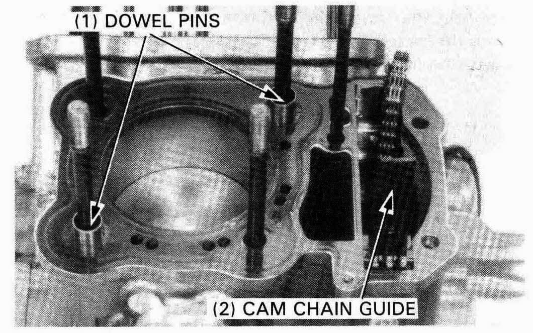
Remove the gasket, dowel pins, and cam chain guide from the cylinder.
Cylinder head
Check the spark plug hole and valve areas for cracks.
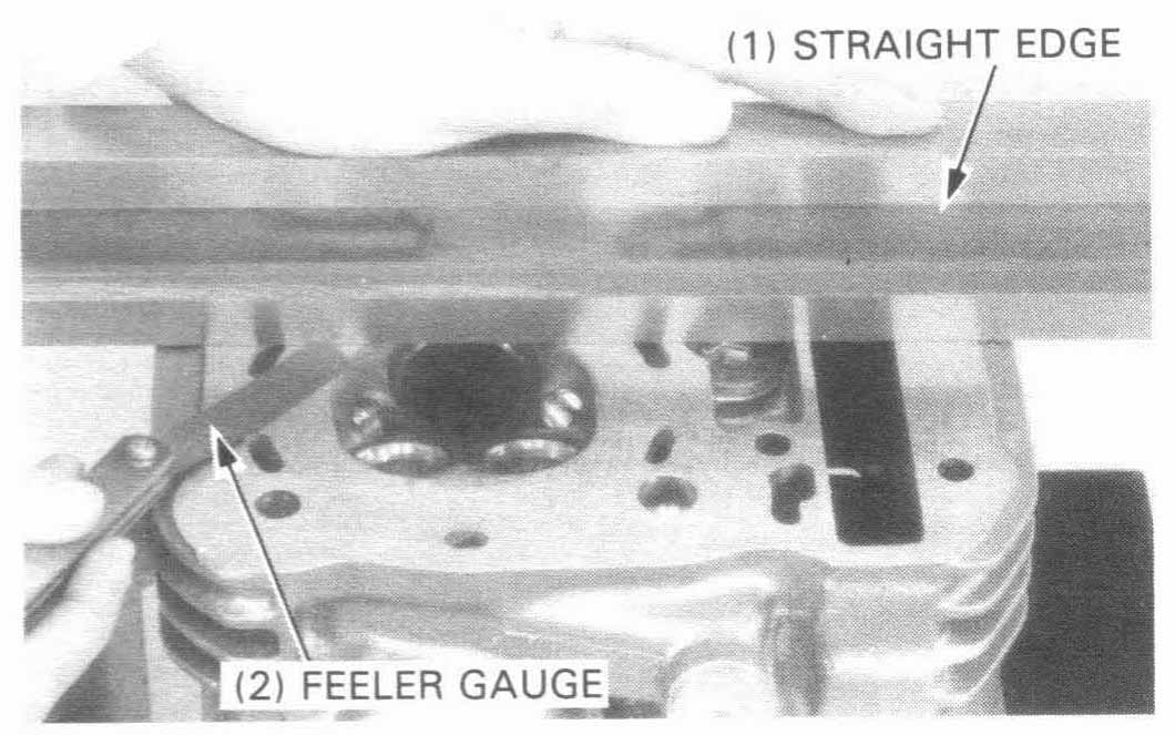
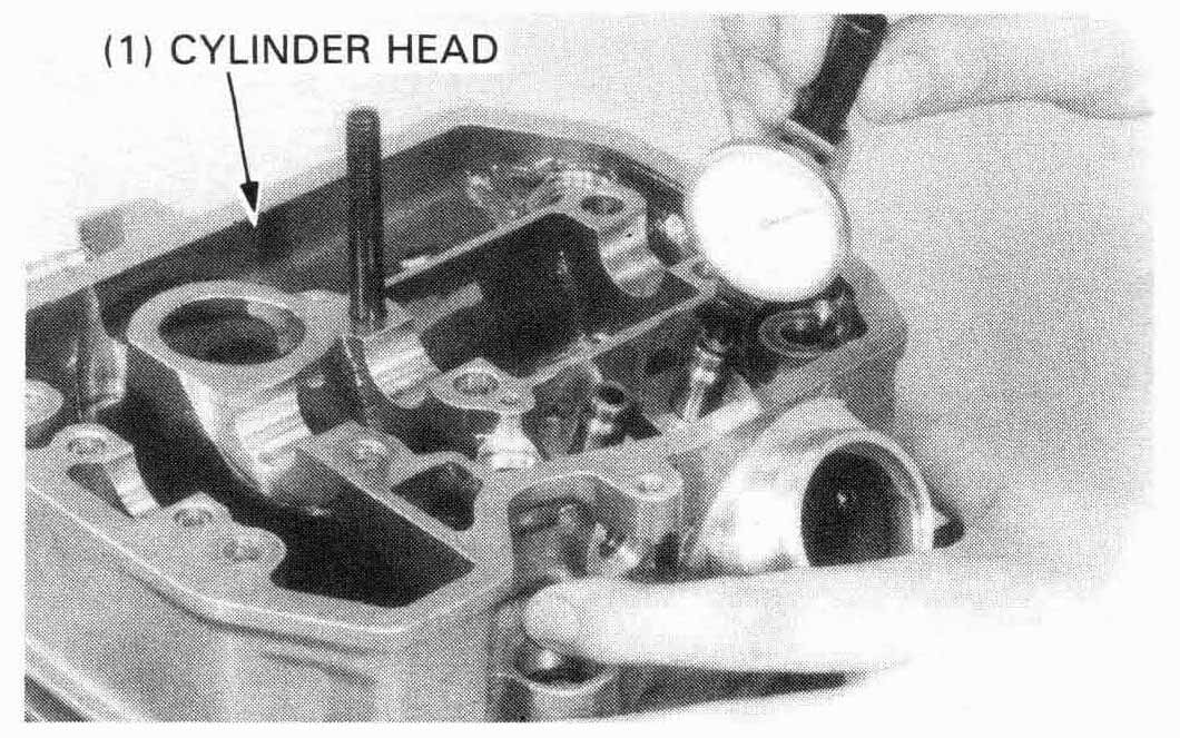
Check the cylinder head for warpage with the straight edge
and feeler gauge.
SERVICE LIMIT: 0.10 mm (0.004 in)

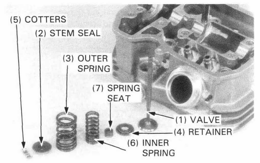
Remove the valve spring cotters, retainers, springs, and valves using a Valve Spring Compressor.
| TOOL: | |
| Valve spring compressor | 07757—0010000 or 07957—3290001 |
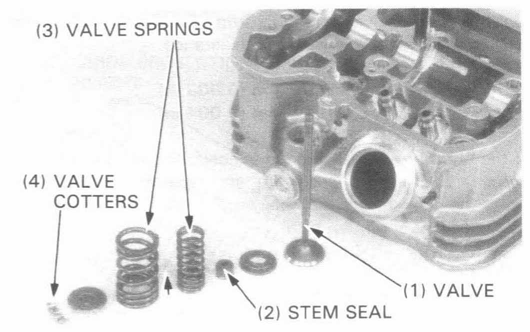
Remove the valve stem seals and valve spring seats.
Remove carbon deposits from the combustion chamber.
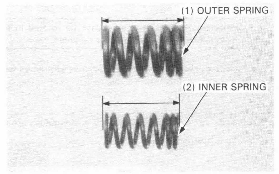
Valve springs
Measure the free length of the inner and outer valve springs.
| SERVICE LIMITS: | ||
| INNER (IN): (EX): | 36.47 mm (1.436 in) 37.51 mm (1.477 in) | |
| OUTER (IN): (EX): | 40.58 mm (1.598 in) 41.25 mm (1.624 in) | |
Replace the springs as a set if they are shorter than the service limits.
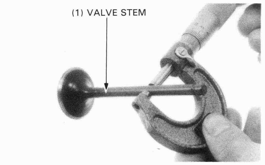
Valve stem-to-guide clearance
Inspect eac valve for bending, burning, scratches, or
abnormal stem wear.
Check valve movement in the guide and measure and record each valve stem O.D.
| SERVICE LIMITS: | IN: | 5.47 mm (0.215 in) |
| EX: | 6.55 mm (0.258 in) |
Measure and record each valve guide I.D.
| SERVICE LIMITS: | IN: | 5.53 mm (0.218 in) |
| EX: | 6.66 mm (0.262 in) |
Subtract each valve stem O.D. from the corresponding guide I.D. to obtain the stem to guide clearance.
| SERVICE LIMITS: | IN: | 0.07 mm (0.003 in) |
| EX: | 0.11 mm (0.004 in) |
If the stem-to-guide clearance exceeds the service limits, determine if a new guide with standard dimentions would bring the clearance within tolerance. If so, replace any guides as necessary and ream to fit.
| TOOLS: | |
| IN: | 07984—2000001 or 07984—200000B (U.S.A. only) |
| EX: | 07984—ZE20001 or 07984—ZE2000B (U.S.A. only) |
If the stem-to-guide clearance exceeds the service limits with new guides, also, replace the valves.
Chill the valve guides in the freezer section of a refrigerator for about an hour.
Heat the cylinder head to 212°F (100°C) with a hot plate or oven. Maximum
allowable temperature is 300°F (150°C).
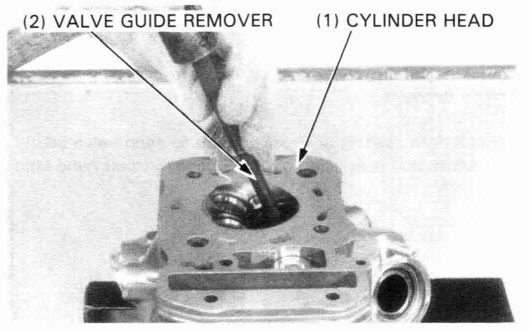
Support the cylinder head and drive out the old guides from the combustion chamber side of the cylinder head.
| TOOLS: | ||
| Valve guide driver | ||
| (IN): | 07742—0010100 | |
| (EX): | 07742—0010200 or 07942—6570100 (U.S.A. only) | |
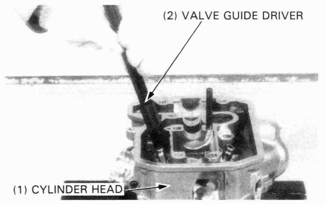
Make note of the valve guide projection specifications (following), then drive in new guides from camshaft side of the cylinder head.
| TOOLS: | ||
| Valve guide driver | ||
| 5.5 mm (IN): | 07742—0010100 | |
| 6.6 mm (EX): | 07742—0010200 | |
| Attachment | ||
| 5.5 mm (IN): | 07943—MF50100 | |
| 6.6 mm (EX): | 07943—MF50200 | |
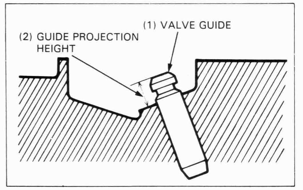
| VALVE GUIDE PROJECTION HEIGHT: | |
| IN: | 19.4 - 19.6 mm (0.76 - 0.77 in) |
| EX: | 17.9 - 18.1 mm (0.70 - 0.71 in) |

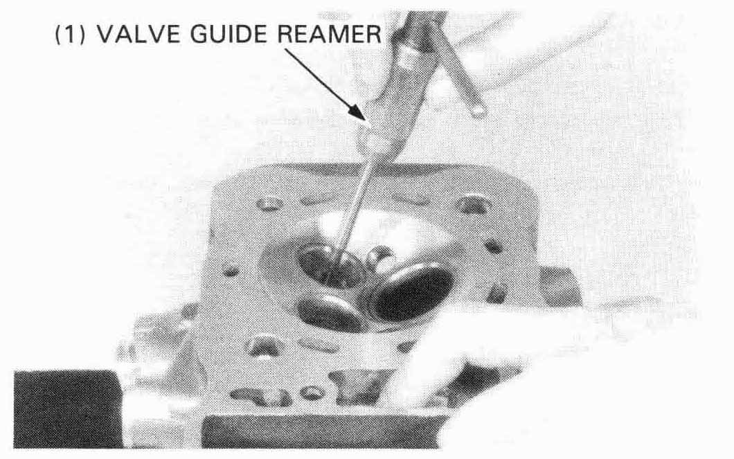
Ream the new valves guids after installation.
Clean the head thoroughly after reaming the valve guides.
| TOOLS: | |
| Valve guide reamer | |
| IN: | 07984—2000001 or 07984—200000B (U.S.A. only) |
| EX: | 07984—ZE20001 or 07984—ZE2000B (U.S.A. only) |
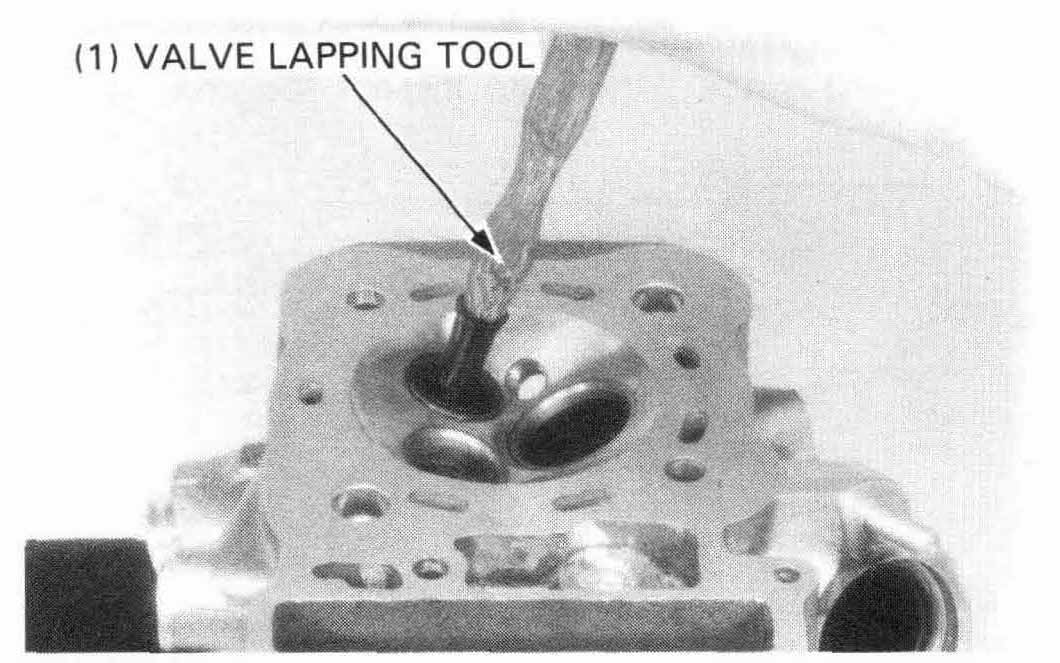
Clean the intake and exhaust valves thoroughly to remove carbon deposits.
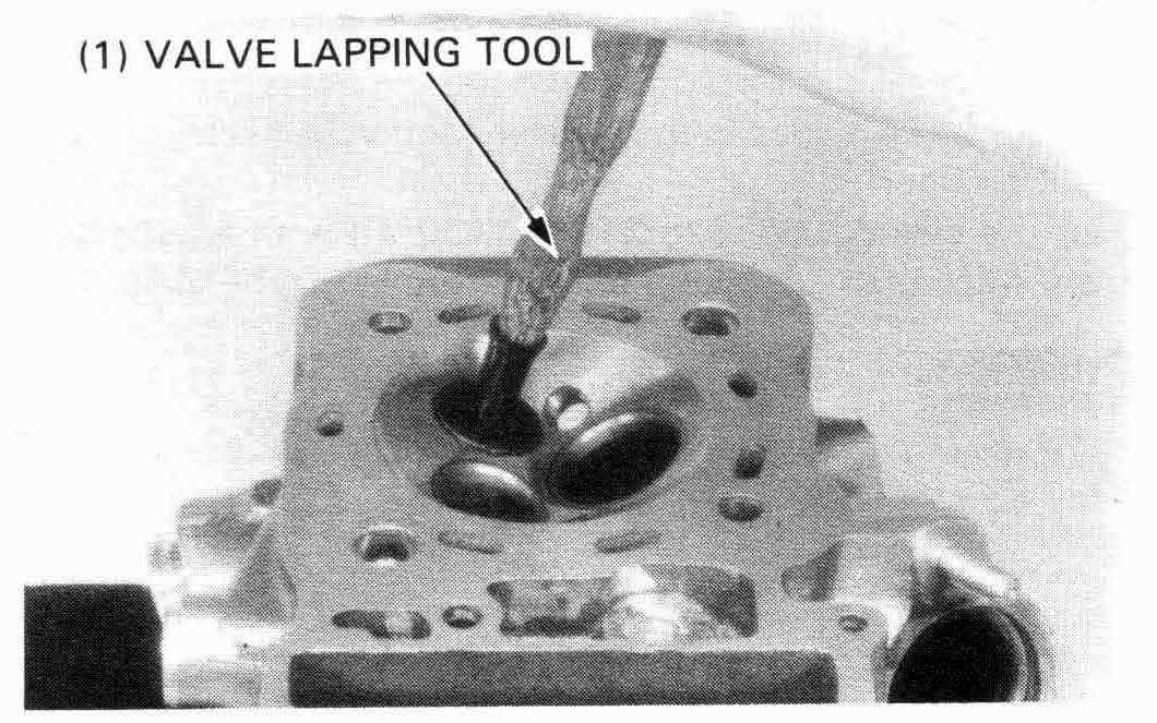
Apply a light coating of Prussian Blue to each valve seat. Lap each valve and seat using a rubber hose or other hand lapping tool.
Remove and inspect each valve.
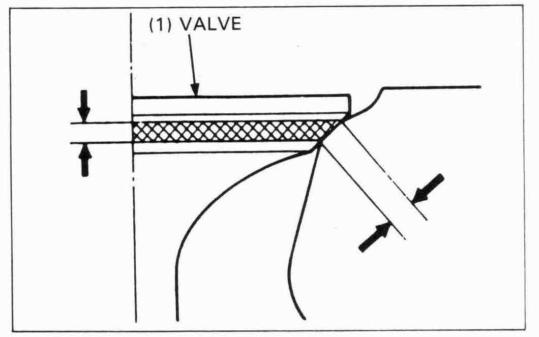
Inspect the width of each valve seat.
| STANDARD: | 0.9 - 1.1 mm (0.035 - 0.043 in) |
| SERVICE LIMIT: | 1.5 mm (0.06 in) |
If the seat is too wide, too narrow, or has low spots, the seat must be ground.
VALVE SEAT CUTTERS
Honda Valve Seat Cutters, grinder or equivalent valve refacing equipment are recommended to correct a worn valve seat.

VALVE SEAT REFACING
Use a 45 degree cutter to remove any roughness or irregularies from the seat.
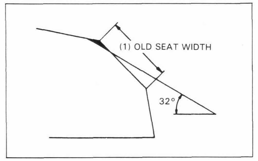
Use a 32 degree cutter to remove the top 1/4 of the existing valve seat material.
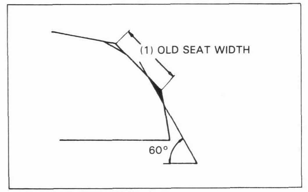
Use a 60 degree cutter to remove the bottom 1/4 of the old seat. Remove the cutter and inspect the area you have refaced.
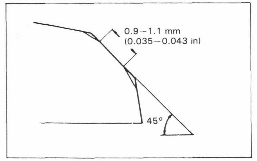
Install a 45 degree finish cutter and cut the seat to the proper width. Make sure that all pitting and irregularities are removed. Refinish if necessary.
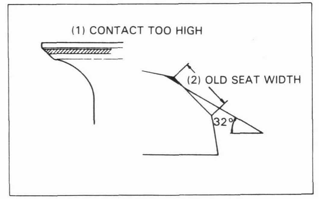
Apply a thin coating of Prussian Blue to the valve seat. Press the valve through the valve guide and onto the seat to make a clear pattern.
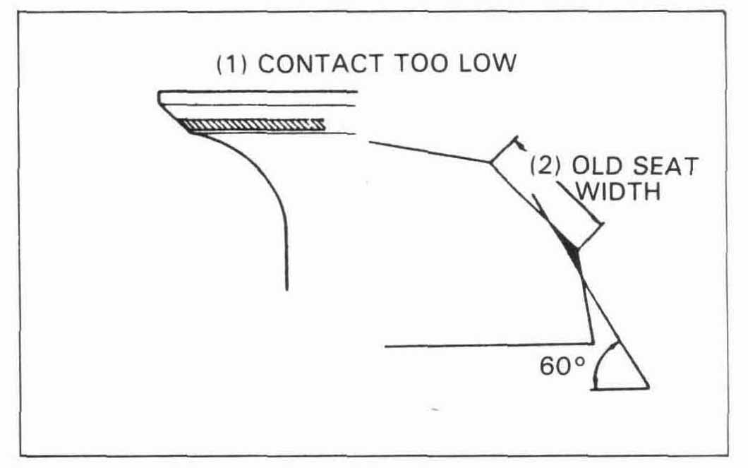
If the contact area is too low on the valve, the seat must be raised using a 60 degree inner cutter.
Refinish the seat to specifications, using a 45 degree finish cutter.
After cutting the seat, apply lapping compound to the valve
face, and lap the valve using light pressure.
After lapping, wash all residual compound off the cylinder
head and valve.
Install the valve spring seats and new stem seals.
Lubricate each valve stem with MoS2 paste grease and insert
the valve into the valve guide. Turn the valve slowly
while inserting to avoid damaging the seals.
Move the valves up and down to check for smooth operation.
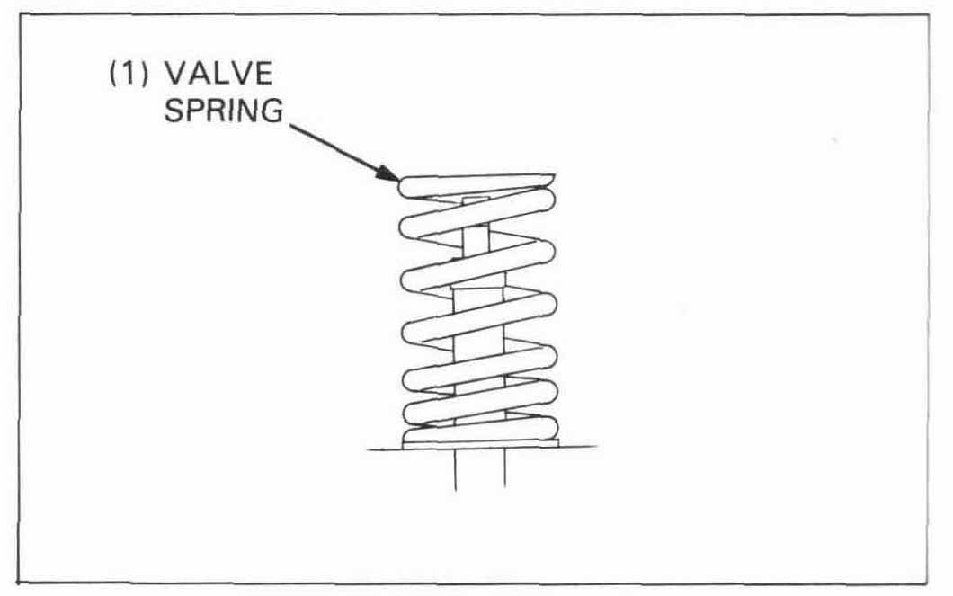
Install the valve springs with the tightly wound coils facing the combustion chamber.
Install the spring retainers.

Compress the springs and install the valve cotters.
| TOOL: | |
| Valve spring compressor | 07757—0010000 or |
| 07957—3290001 |

Tap the valve stems gently with a soft hammer to firmly seat the cotters.
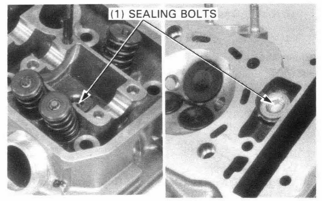
Apply locking agent to the threads of the sealing bolts and tighten them, if removed.
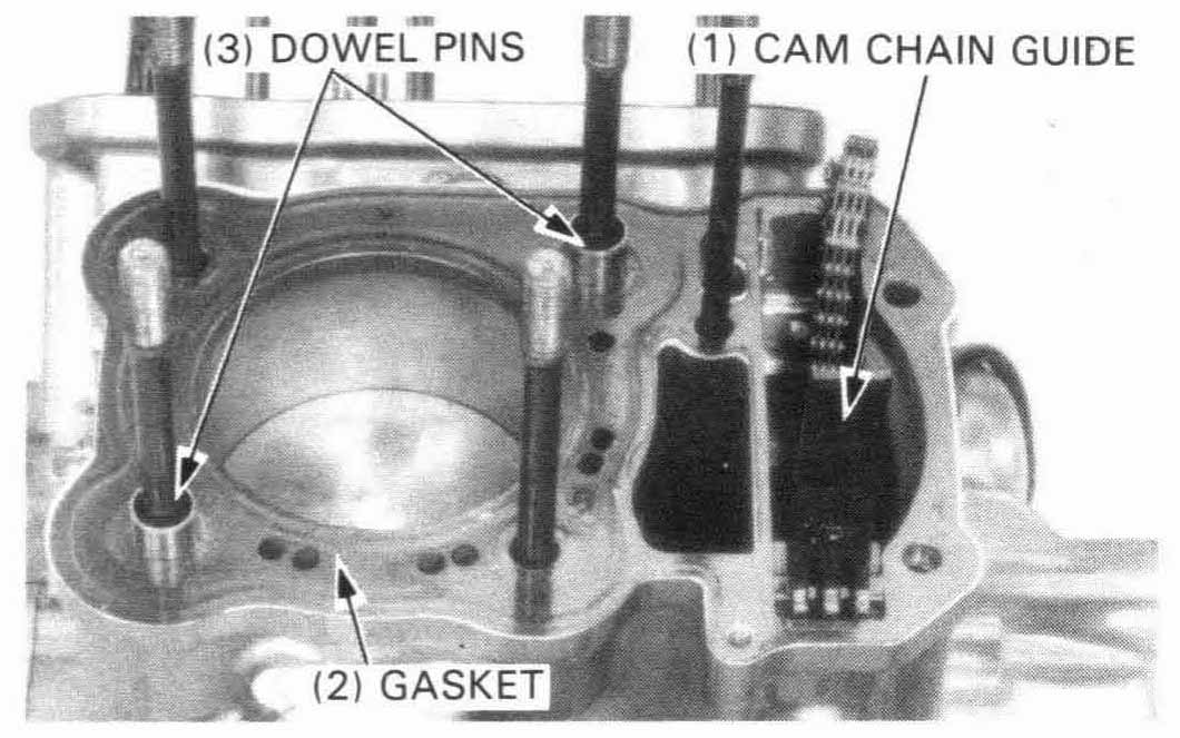
Install the cam chain guide into the cylinder.
Make sure that the cam chain guide bosses are in the grooves of cylinder.
Clean the cylinder head surface of any gasket material.
Install the dowel pins and a new head gasket.
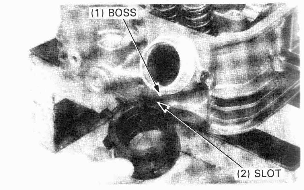
Install the carburetor insulator on the cylinder head, aligning the
boss on the cylinder head with the slot in the insulator.
Tighten the screw securely.
Install the cylinder head.
Reinstall the upper exhaust port stud securely.
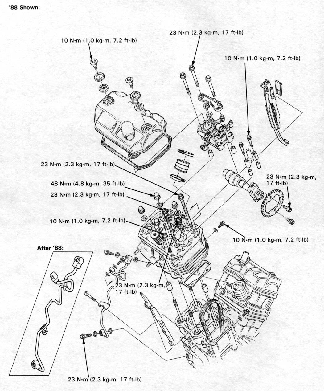
Install the 10mm nut/washer, 8 mm nut/washer, 8 mm bolt/washer,
and 6 mm bolt and tighten them in a crosscross pattern
in 2 or 3 steps.
| TORQUE: | |||
| 10 | mm nut: | 48 N•m (4.8 kg-m, 35 ft-lb) | |
| 8 | mm bolt: | 23 N•m (2.3 kg-m, 17 ft-lb) | |
| 8 | mm nut: | 23 N•m (2.3 kg-m, 17 ft-lb) | |
| 6 | mm bolt: | 10 N•m (1.0 kg-m, 7.2 ft-lb) | |
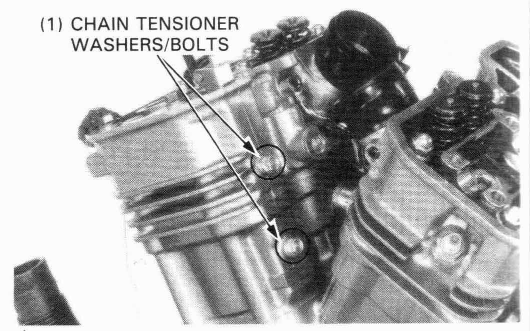
Install the following:
| TORQUE: Camn chain tensioner bolt: | ||
| 10 N•m (1.0 kg-m, 7.2 ft-lb) | ||
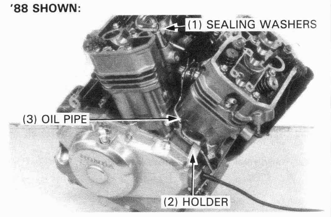
Check the oil pass pipe bolts and oil pass pipe for clogging or bending.
Install the oil pass pipe, new sealing washers, oil
pass pipe bolts, and the pipe holder bolt.
Tighten the bolts.
| TORQUE: | ||||
| Oil pass pipe bolt: | ||||
| 7 | mm: | 10 N•m (1.0 kg-m, 7.2 ft-lb) | ||
| 8 | mm: | 23 N•m (2.3 kg-m, 17 ft-lb) | ||
Install the following:
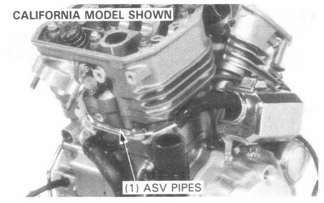
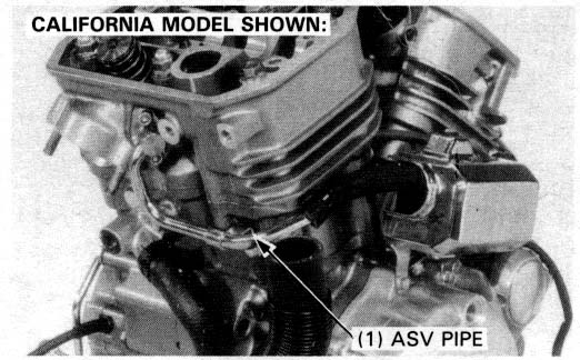
California model only:
Install the ASV pipes onto the cylinder.
All models:
install the cylinder head cover (page 9-20)
Reinstall the radiator, and exhaust pipes.
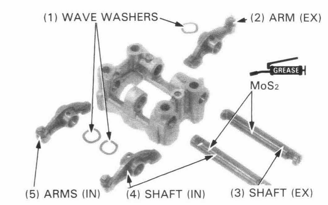
Apply MoS2 paste grease to the rocker arm shafts.
Install the rocker arms, rocker arm shafts, and wave washers
in the camshaft holders.

Position the grooves in the rocker arm shafts vertically, aligning
the bolt holes of the holder with the holes of the shafts.
Apply MoS2 grease to the rocker arm slipper faces.
FRONT CAMSHAFT ONLY
Turn the crankshaft counterclockwise and align the “RT” mark on the flywheel with the index mark on the timing hole. Make sure the REAR cam lobes are all facing UP. If they are not, turn the crankshaft counterclockwise one revolution so that the REAR cam lobes are all facing UP. (NOTE: This is the valve overlap position.)
Continue turning the crankshaft counterclockwise (128°) until the “FT” mark on the flywheel aligns with the index masrk on the timing hole (approximately 3/8 turn).

Install the dowel pins into the cylinder head.
Install the camshaft in the cylinder head through the cam chain and install the cam sprocket on the camshaft.
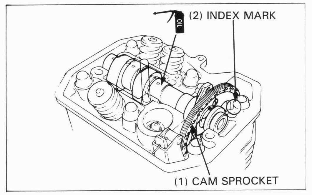
With the cam lobes all facing down, align the timing marks (index lines) on the cam sprocket with the top of the cylinder head.
Place the cam chain on the sprocket.
lnstall the cam sprocket on the camshaft flange and recheck that the timing marks (index lines) align with the top of the cylinder head.
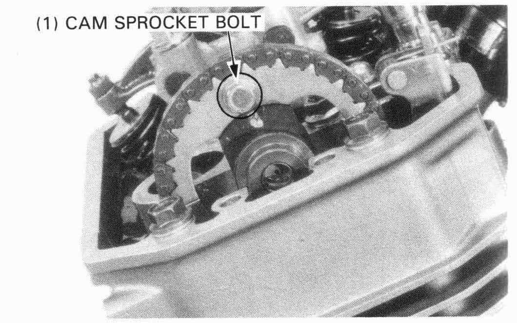
Align the cam sprocket bolt holes in the cam sprocket and camshaft, install and tighten the cam sprocket bolt.
TORQUE: 23 N•m (2.3 kg-m, 17 ft-lb)
Install the holder, oil plate, 8 mm bolts, 8 mm nut and 6 mm bolts.
| TORQUE: | ||
| 8 mm bolt: | 23 N•m (2.3 kg-m, 17 ft-lb) | |
| 8 mm nut: | 23 N•m (2.3 kg-m, 17 ft-lb) | |
| 6 mm bolt: | 10 N•m (1.0 kg-m, 7.2 ft-lb) | |
Turn the crankshaft counterclockwise 360° and install the
other sprocket bolt.
lnstall the end holder.
After installing the front cylinder camshaft, turn the crankshaft counterclockwise 232° (approximately 5/8 turn) and align the RT mark with the index on the timing hole, then install the rear cylinder camshaft using the same procedure as for the front cylinder.
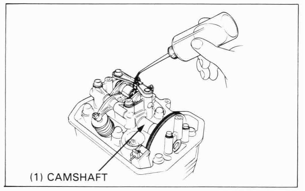
Lubricate the cam lobes with fresh engine oil.
If the cylinder head was removed with the engine in the frame, install the following:
REAR CAMSHAFT ONLY
Turn the crankshaft counterclockwise and align the “FT” mark on the flywheel with the index mark on the timing hole. Make sure the FRONT cam lobes are all facing DOWN. If they are not, turn the crankshaft counterclockwise one revolution so that the FRONT cam lobes are all facing DOWN.
Continue turning the crankshaft counterclockwise (232°) until the “RT” mark on the flywheel aligns with the index mark on the timing hole (approximately 5/8 turn).
Place the camshaft into correct position with the cam lobes all
facing down.
Install the cam sprocket and camshaft holders using the same
procedure as for the front cylinder (page 9-17).
FRONT AND REAR CAMSHAFTS
Turn the crankshaft counterclockwise and align the “FT” mark on the flywheel with the index mark on the timing hole.
Install the front camshaft with all the cam lobes facing DOWN. Align the index marks on the cam sprocket with the top of the cylinder head.
Continue turning the crankshaft counterclockwise (232°) until the “RT” mark on the flywheel aligns with the index mark on the tlming hole (approximately 5/8 turn).
Install the rear camshaft with all the cam lobes facing DOWN. Align the index lines on the cam sprocket with the top of the cylinder head.
Remove the 2 mm pin holding the cam chain tensioner wedge A.
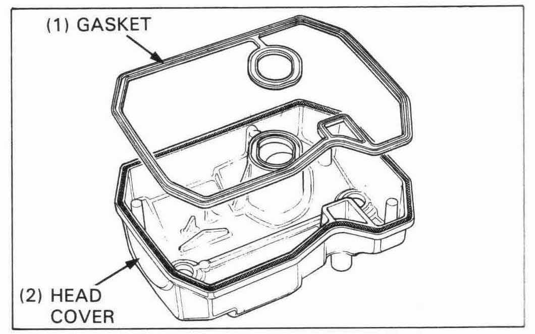
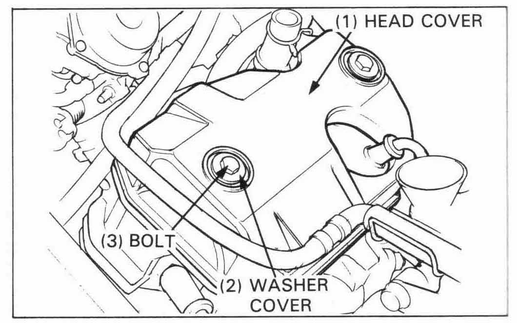
Install the cylinder head cover, rubber washer, washer cover, and
cylinder head cover bolts.
Tighten the cover bolts.
TORQUE: 10 N•m (1.0 kg-m, 7.2 ft-lb)
Connect the water hose pipe and stall the spark plug caps.
Install the following parts:
Fill the cooling system (page 5-3)