really big verson
Hawkworks.net main page
Manual main index
| SERVICE INFORMATION | 6-2 |
| ENGINE REMOVAL | 6-3 |
| ENGINE INSTALLATION | 6-5 |
| Engine dry weight | 61 kg (134 lb) |
| Oil capacity | 2.8 lit (2.94 US qt, 2.46 Imp qt) at disassembly |
| Coolant capacity | 2.0 lit (1.89 US qt, 2.27 Imp qt) total |
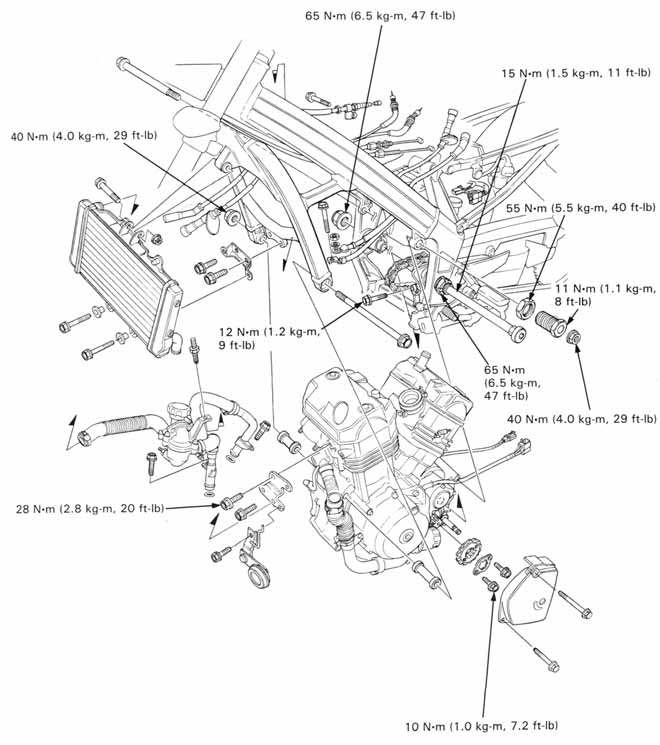
| Muffler mounting bolt | 27 N•m (2.7 kg-m, 20 ft-lb) |
| Exhaust pipe joint nut | 27 N•m (2.7 kg-m, 20 ft-lb) |
| Gearshift arm bolt | 12 N•m (1.2 kg-m, 9 ft-lb) |
| Drive sprocket bolt | 10 N•m (1.0 kg-m, 7.2 ft-lb) |
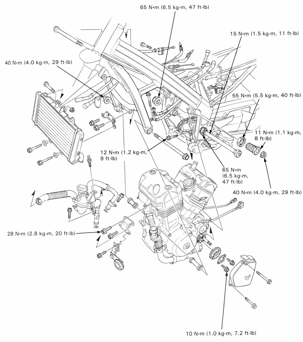
| Swingarm pivot nut | 65 N•m (6.5 kg-m, 47 ft-lb) |
| Swingarm pivot lock nut | 65 N•m (6.5 kg-m, 47 ft-lb) |
| Swingarm pivot adjusting bolt | 15 N•m (1.5 kg-m, 11 ft-lb) |
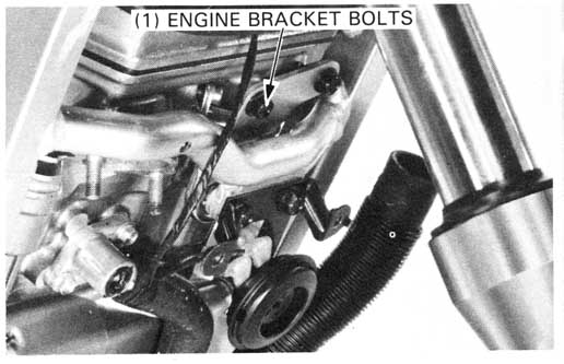
| Front engine bracket bolt | 28 N•m (2.8 kg-m, 20 ft-lb) |
| Front engine mounting bolt | 40 N•m (4.0 kg-m, 29 ft-lb) |
| rear upper engine mounting bolt | 40 N•m (4.0 kg-m, 29 ft-lb) |
| --mounting bolt lock nut | 55 N•m (5.5 kg-m, 40 ft-lb) |
| --mounting bolt adjusting bolt | 11 N•m (1.1 kg-m, 8 ft-lb) |
| Fuel tank mounting bolt - front | 12 N•m (1.2 kg-m, 9 ft-lb) |
| Fuel tank mounting bolt - rear | 22 N•m (2.2 kg-m, 13 ft-lb) |
| Special | |
| Lock nut wrench | 07908—ME90000 |
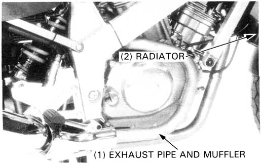
Remove the following:
Remove the gearshift arm from the gearshift spindle.
Loosen the drive chain (page 3-12).
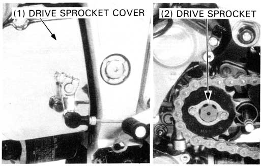
Remove the drive sprocket cover (page 8-2),
then remove the sprocket from the drive chain by removing two
sprocket bolts and the plate.
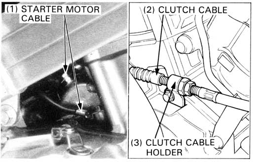
Disconnect the following electrical connections:
Disconnect the following cooling system connections:
Disconnect the clutch cable from the clutch lifter arm by removing the holder bolt.
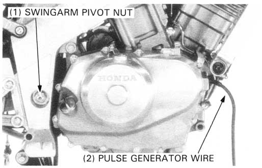
Remove the swingarm pivot nut.
Place a floor jack or other adjustable support under the engine.
Remove the engine upper bracket bolts and bracket.

Remove the front engine lower mounting bolt.
Loosen the rear engine upper mounting bolt lock nut and
remove the rear engine upper mounting and adjusting bolts.
Remove the swingarm pivot adjusting bolt lock nut.
| TOOL: | |
| Lock Nut wrench | 07908—ME90000 |

Install the engine into the frame correctly.
Engine installation is essentially the reverse order of removal. Use a floor jack or other adjustable support to carefully manuever the engine into place.
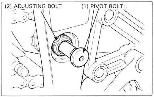
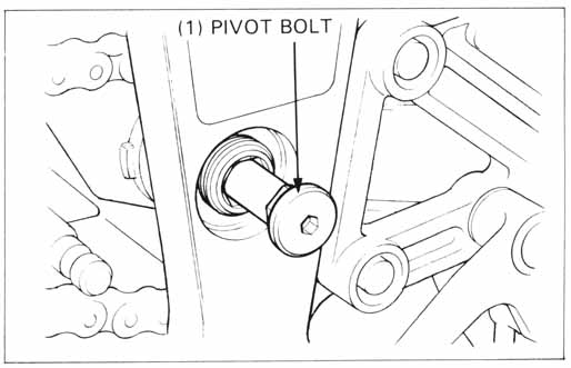
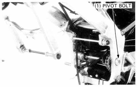
Insert the swingarm pivot bolt while aligning the serrations of the pivot bolt and adjusting bolt.
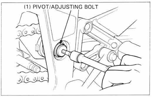
Turn the pivot bolt with the adjusting bolt clockwise fully to seat the swingarm left pivot collar.
Tighten the bolt to the specified torque.
TORQUE: 15 N•m (1.5 kg-m, 11 ft-lb)
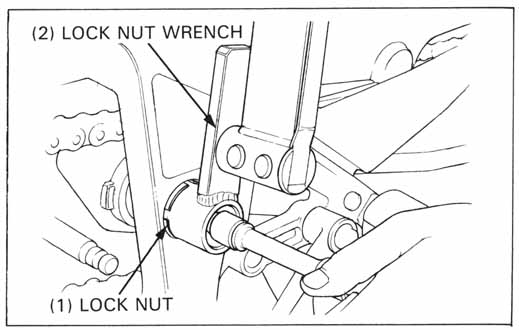
Install the lock nut onto the adjusting bolt.
Tighten the lock nut to the specified torque while holding the
pivot bolt and adjusting bolt together.
| TORQUE: | ||
| Actual: | 65 N•m (6.5 kg-m, 47 ft-lb) | |
| Indicated: | 59 N•m (5.9 kg-m, 43 ft-lb) | |
| TOOL: | |
| Lock nut wrench | 07908—ME9000O |
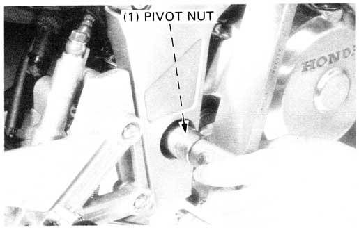
Install the swingarm pivot nut and tighten it to the specified torque.
TORQUE: 65 N•m (6.5 kg-m, 47 ft-lb)
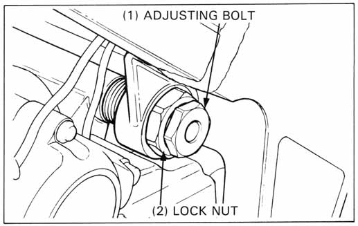
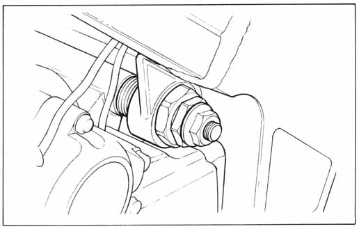
Install the rear engine upper mounting adjusting bolt.
Turn the mounting adjust bolt clockwise fully to seat the engine mount.
Tighten to the specified torque.
TORQUE 11 N•m (1.1 kg-m, 8 ft-lb)
Install the lock nut onto the adjusting bolt.
TORQUE 55 N•m (5.5 kg-m, 40 ft-lb)
Install the rear engine upper mounting bolt and tighten it to the specified torque.
TORQUE: 40 N•m (4.0 kg-m, 29 ft-lb)