Hawkworks.net main page
Manual main index
| SERVICE INFORMATION | 11-1 |
| TROUBLESHOOTING | 11-2 |
| CRANKCASE SEPARATION | 11-3 |
| CRANKSHAFT/CONNECTING ROD | 11-4 |
| TRANSMISSION | 11-9 |
| CRANKCASE | 11-11 |
| TRANSMISSION ASSEMBLY/INSTALLATION | 11-14 |
| CRANKCASE ASSEMBLY | 11-16 |
Unit: mm (in)
| ITEM | STANDARD | SERVICE LIMIT | ||
| Crankshaft/ connecting rod | Connecting rod big end side clearance | 0.05-0.20 (0.002-0.008) | 0.3 (0.012) | |
| Crankpin oil clearance | 0.028-0.052 (0.0011-0.0020) | 0.3 (0.012) | ||
| Main journal oil clearance | 0.025-0.041 (0.001-0.016) | 0.05 (0.002) | ||
| Crankshaft runout | — | 0.05 (0.002) | ||
| Transmission | Gear I.D | C1 | 14.000-14.021 (0.9449-0.9457) | 24.03 (0.946) |
| M4, M5, C2, C3 | 28.000-28.021 (1.1024-1.1032) | 28.03 (1.103) | ||
| Gear bushing O.D. | C1 | 23.959-23.980 (0.9433-0.9441) | 24.95 (0.982) | |
| M4, M5, C2, C3 | 27.959-27.980 (1.1007-1.1016) | 27.95 (1.100) | ||
| Gear bushing I.D. | C1 | 20.016-20.037 (0.7880-0.7889) | 20.05 (0.789) | |
| M4, C2, C3 | 25.000-25.021 (0.9843-0.9851) | 25.03 (0.985) | ||
| Bushing-to-shaft clearance | M4, C3 | 0.020-0.062 (0.0008-0.0024) | 0.08 (0.003) | |
| C2 | 0.010-0.049 (0.0004-0.0019) | 0.07 (0.003) | ||
| Gear-to-bushing clearance | M4, M5, C1, C2, C3 | 0.020-0.062 (0.0008-0.0024) | 0.08 (0.003) | |
| Mainshaft O.D. | M4 bushing | 24.959-24.980 (0.9826-0.9835) | 24.95 (0.982) | |
| Countershaft O.D. | C1 bushing | 19.980-19.993 (0.7866-0.7871) | 19.97 (0.786) | |
| C2 bushing | 24.972-24.990 (0.9831-0.9839) | 24.96 (0.983) | ||
| C3 bushing | 24.959-24.980 (0.9826-0.9835) | 24.95 (0.982) | ||
| Shift fork/fork-shaft | Claw thickness | 5.93-6.00 (0.233-0.236) | 5.83 (0.230) | |
| Right and left shift fork I.D. | 13.000-13.018 (0.5118-0.5125) | 13.03 (0.513) | ||
| Shaft O.D. | 12.966-12.984 (0.5105-0.5112) | 12.96 (0.510) | ||
| Shift drum O.D. (at the left side journal) | 11.966-11.984 (0.4711-0.4718) | 11.96 (0.471) | ||
| Connecting rod bearing cap nut | 34 N•m (3.4 kg-m, 25 ft-lb) | |
| Crankcase 8 mm stud bolt | 20-30 N•m (2.0-3.0 kg-m, 14-22 ft-lb) | |
| 10 mm stud bolt | 30-50 N•m (3.0-5.0 kg-m, 22-36 ft-lb) | |
| Special | |
| Main bearing driver attachment | 07HMF—MM90400 |
| Bearing remover set | 07936—3710001 |
| — remover handle | 07936—3710100 |
| — bearing remover set | 07936—371 0600 |
| — remover weight | 07741—0010201 or 07936—3710200 U.S.A. only |
| Common | |
| Driver | 07749—0010000 |
| Attachment, 42 x 47 mm | 07746—0010300 |
| Pilot, 20 mm | 07746—0040500 |
| Attachment, 52 x 55 mm | 07746—0010400 |
| Pilot, 22 mm | 07746—0041000 |
| Pilot, 25 mm | 07746—0040600 |
Excessive noise
Hard to shift
Transmission jumps out of gear
Remove the engine from the frame (Section 6).
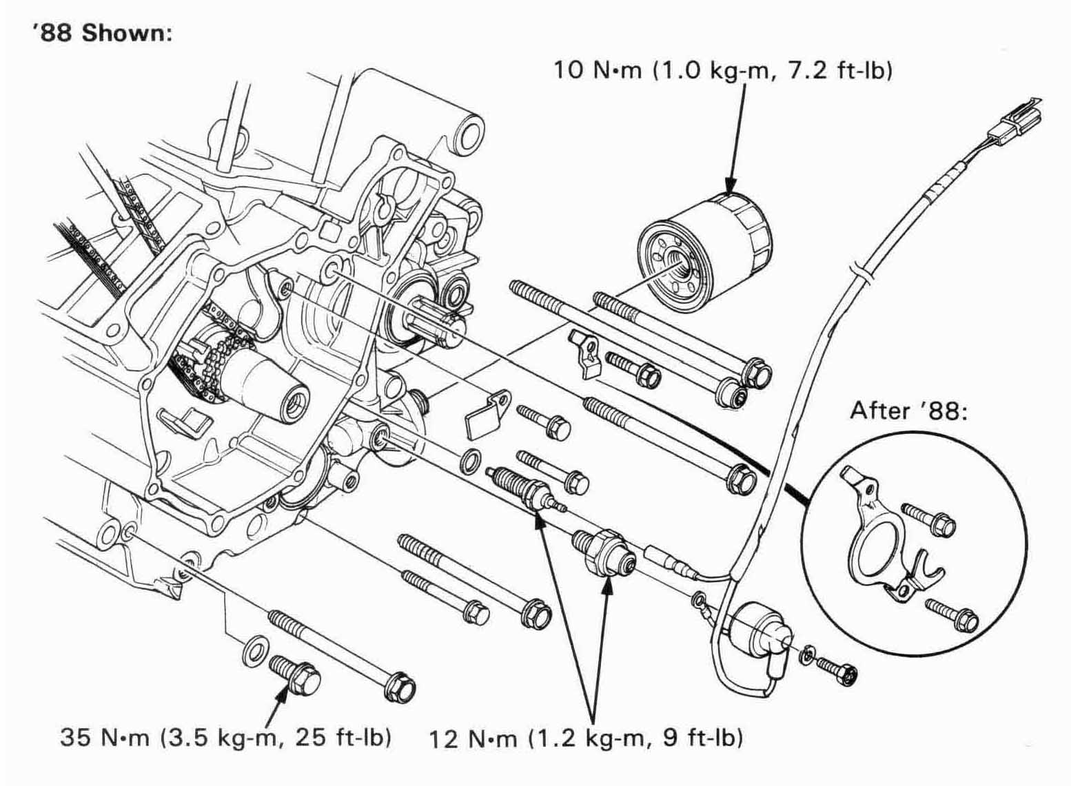
Remove the oil filter.
Refer to the service information (page 11-1)
for the parts that
must be removed before the separating the crankcase.
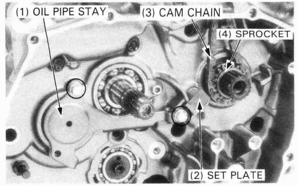
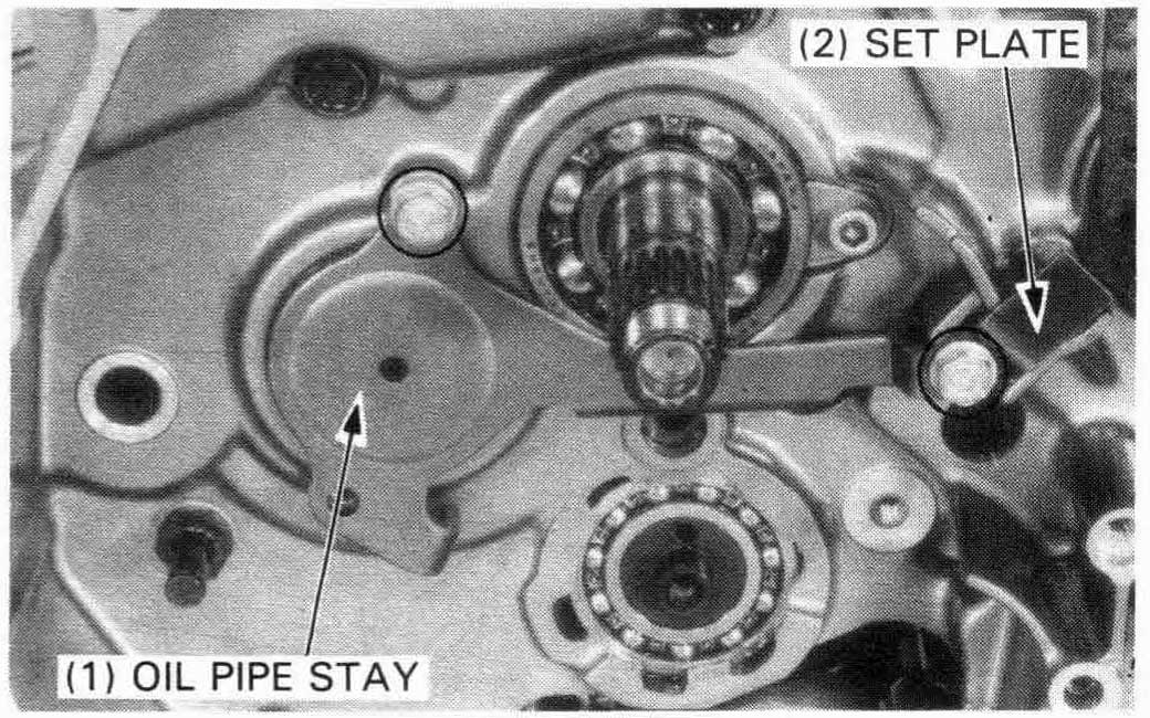
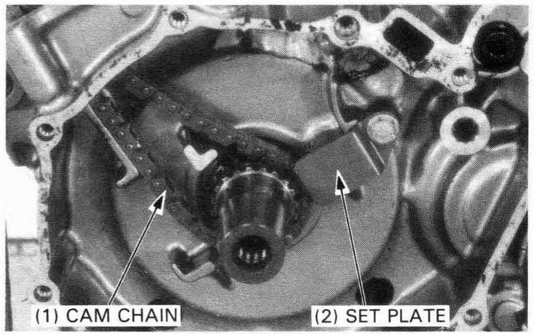
Remove the oil pipe stay and cam chain tensioner set plate by removing the bolts.
Remove the rear cam chain and cam chain drive sprocket.
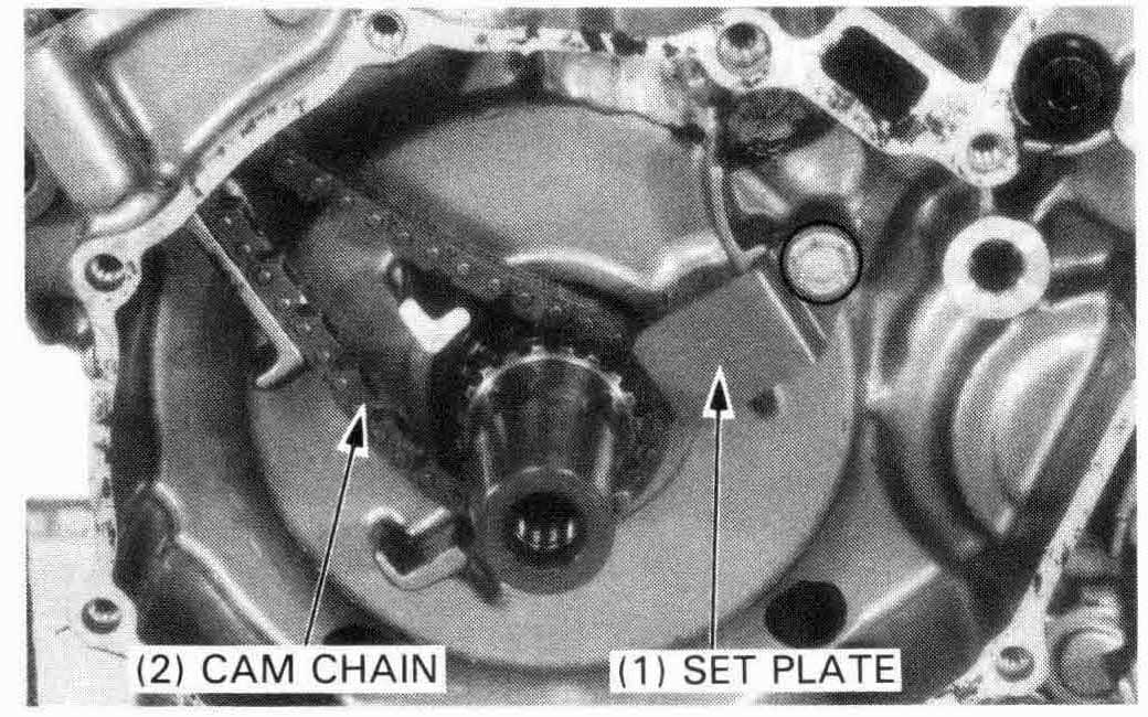
Remove the bolt and cam chain tensioner set plate.
Remove the front cam chain from the crankshaft.
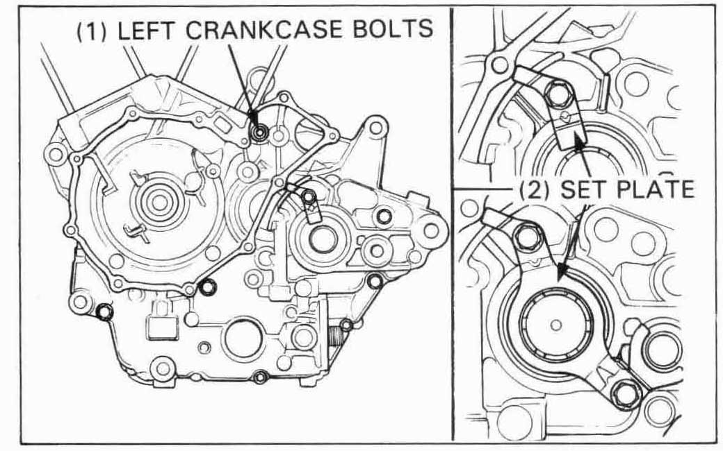
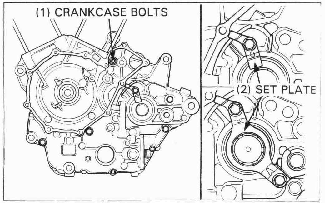
Remove the 8 mm bolts and 6 mm bolts from the left crankcase.
’88 Only:
Remove the countershaft set plate bolt and the plate.
After ’88:
Remove the countershaft set plate bolts (2 pcs.) and the plate.
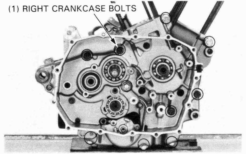
’88, After ’88:
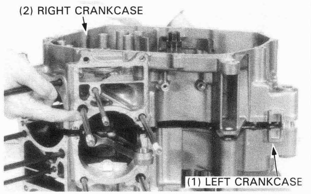
Remove the 8 mm bolts and 6 mm bolts from the right crankcase.
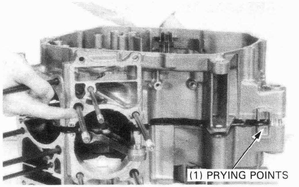
Place the left crankcase side down and separate the right crankcase from the left crankcase while prying where indicated at the points shown and tapping the cases at several locations with a soft hammer.

Remove the dowel pins and clean the crankcase halves of any sealant material.
Remove the crankshaft from the left crankcase.
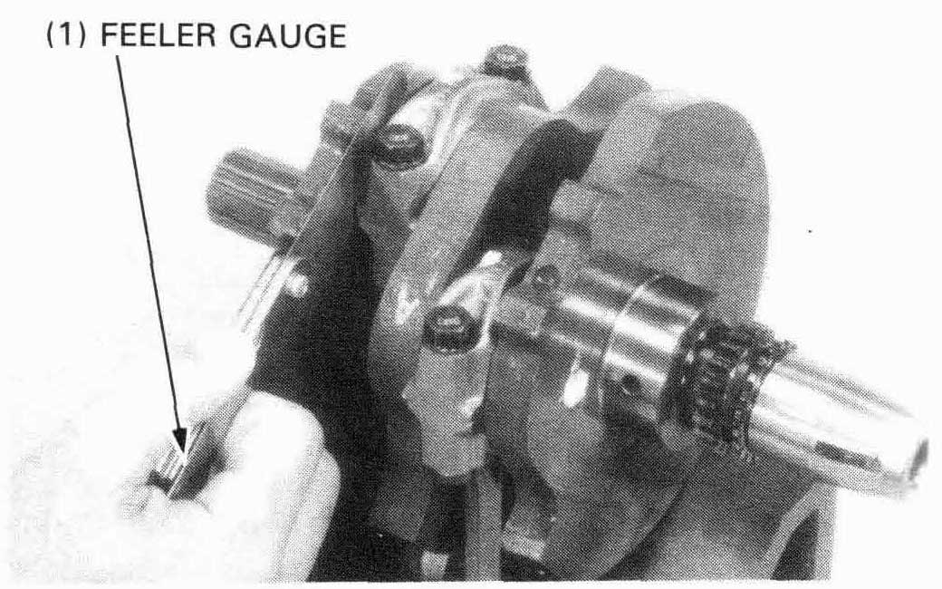
Check the connecting rod side clearance with feeler gauge.
SERVICE LIMIT: 0.30 mm (0.012 in)
If either side clearance exceeds the service limit, replace the
connecting rod and recheck.
If still beyond the limit, replace the crankshaft.
Inspect the crankshaft for rough spots or damage.
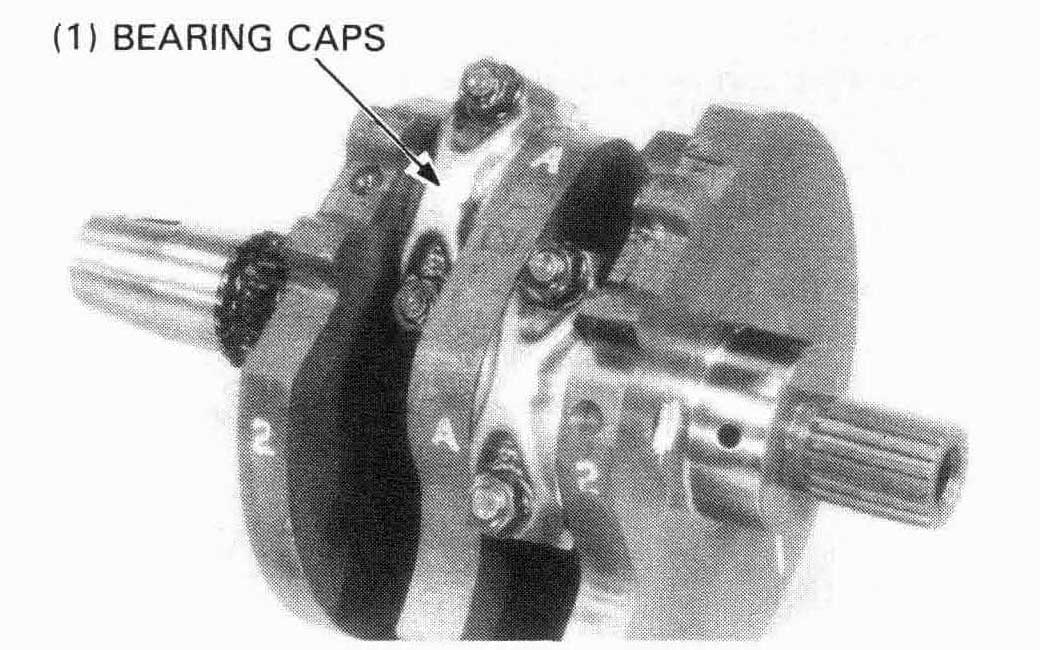
Remove the connecting rod bearing caps noting their locations.

Place the crankshaft on a stand or V blocks.
Set a dial indicator on the main journals. Rotate the crankshaft
two revolutions and read the runout.
| SERVICE LIMIT: 0.05 mm (0.002 in) |
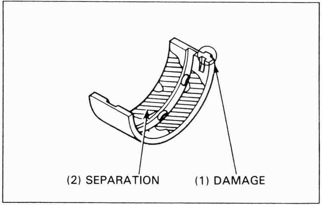
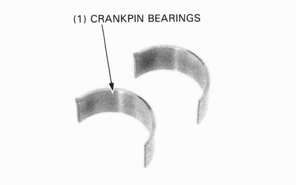
Inspect the bearing inserts for damage or separation
Clean all oil from the bearing inserts and crankpins.
Put a piece of plastigauge on each crankpin avoiding the oil hole.
Install the bearing caps and rods on the correct crankpins, and tighten them evenly.
TORQUE: 34 N-rn (3.4 kg-rn, 25 ft-lb)

Remove the caps and measure the compressed plastigauge at its widest point on each crankpin to determine the oil clearance.
SERVICE LIMIT: 0.08 mm (0.003 in)
If the rod bearing clearance is beyond tolerance, select redacement bearings.
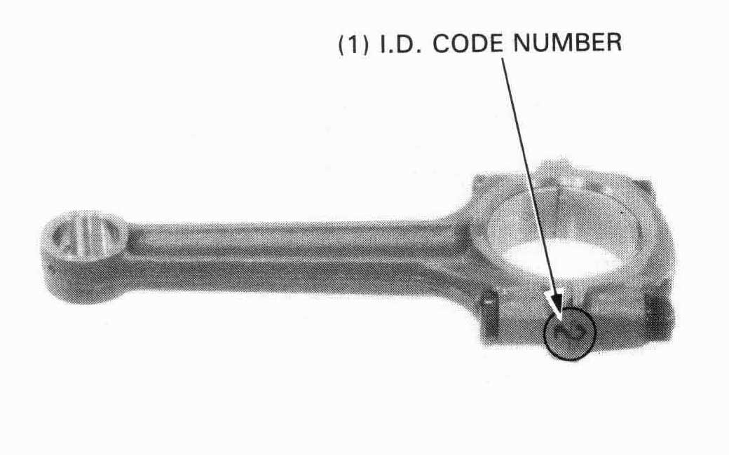
Determine the connecting rod I.D. code number.
The code will be either a number 1 or 2 located on the rod in
the area shown.
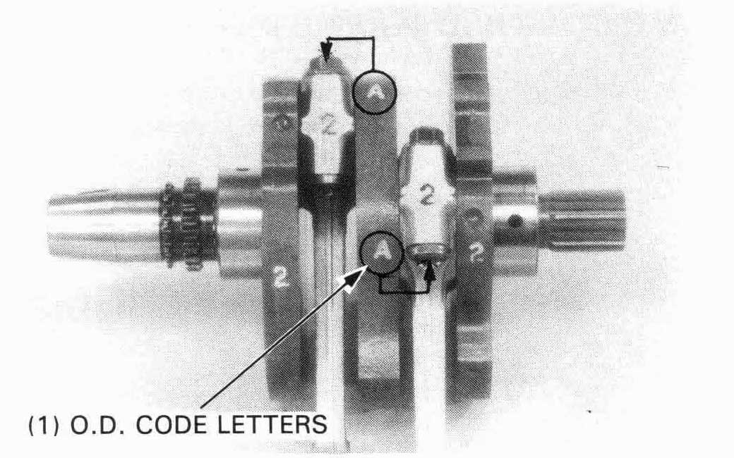
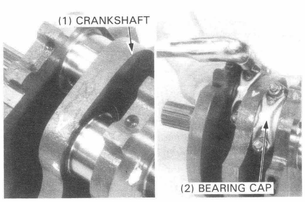
Determine the corresponding crankpin O.D. code (or measure the crankpin O.D.). The code will be either a letter A or B on the crank weight.
Cross reference the crankpin and connecting rod codes to determine the replacement bearing color.
| Crankpin O.D. code Connecting rod I.D. code | A | B | |
| 39.982-39.990 mm (1.5741-1.5744 in) | 39.974-39.983 mm (1.5738-1.5741 in) | ||
| 1 | 43.000-43.008 mm (1.6929-1.6932 in) | C (BROWN) | B (BLACK) |
| 2 | 43.008-43.016 mm (1.6932-1.6935 in) | B (BLACK) | A (BLUE) |
| BEARING INSERT THICKNESS | |
| A (BLUE): | 1.495- 1.499 mm (0.0589-0.0590 in) |
| B (BLACK): | 1.491 - 1.495 mm (0.0587-0.0589 in) |
| C (BR0WN): | 1.487- 1.491 mm (0.0585-0.0587 in) |
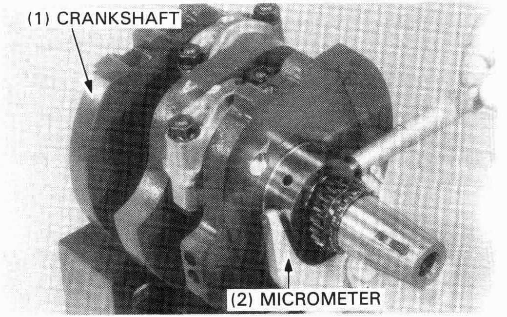
Measure the main journal O.D. and record it.

Measure the main journal bearing I.D. and record it.
Calculate the clearance between the main journal and the main bearing.
SERVICE LIMIT: 0.06 mm (0.002 in)
If the oil clearance is beyond the service limit, select a replacement bearing as follows:
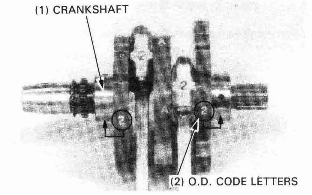
Determine the crankshaft main journal O.D. code. The code will be either a number 1 or 2 on the crank weight.
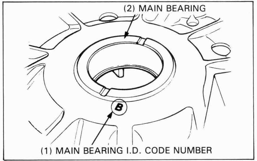
Determine the corresponding main bearing I.D. code. The code will be either a letter A or B on the crankcase.
| Choose replacement main bearings in accordance with the table below. | MAIN JOURNAL O.D. CODE (on crank weight) | |||
| 1 | 2 | |||
| 44.992-45.000mm (1.7713-1.7717 in) | 44.984-44.992 mm (1.7710-1.7713) | |||
| MAIN BEARING I.D. CODE (on crankcase) | A | 48.990-49-000 mm (1.9287-1.9291 in) | C (BROWN) | B (BLACK) |
| B | 49.000-49.010 mm 1.9291-1.9259 in) | B (BLACK) | A (BLUE) | |
| BEARING INSERT THICKNESS | |
| A (BLUE): | 2.003-2.013 mm (0.0789-0.0793 in) |
| B (BLACK): | 1.998-2.008 mm (0.0787-0.0791 in) |
| C (BROWN): | 1.993-2.003 mm (0.0785-0.0789 in) |
Press the main bearing out of the crankcase using a hydraulic press and special tools.
| TOOLS: | |
| Driver | 07749—0010000 |
| Main bearing remover attachment | 07HMF—MM90400 |
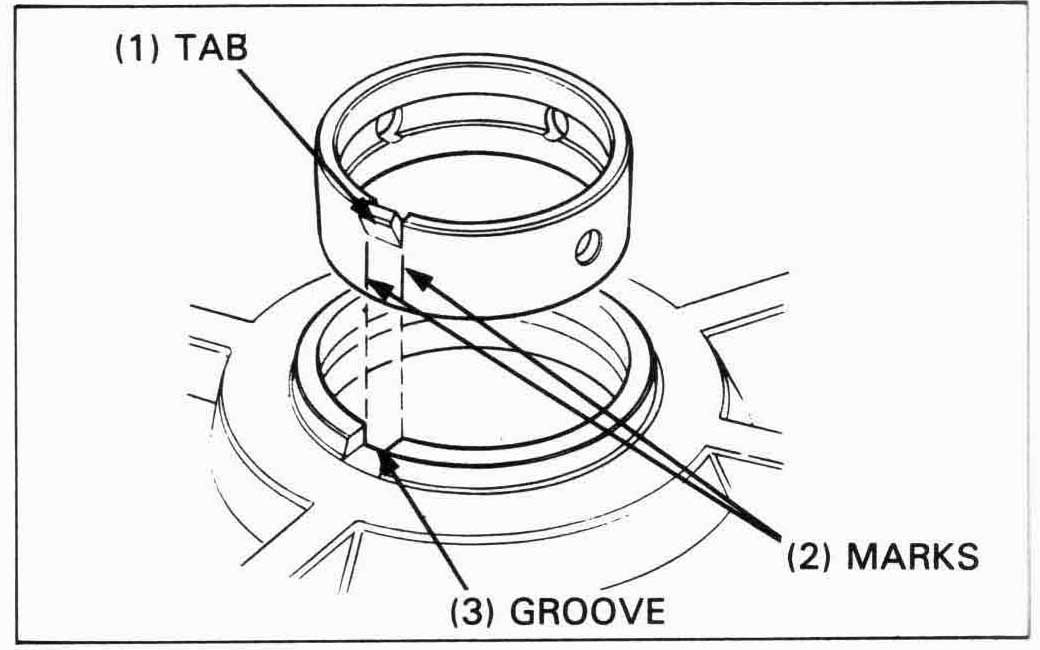
Mark a vertical line below each side of the bearing tab.
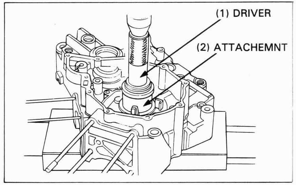
Apply molybdenum disulfide grease to the outer surface of the main bearing.
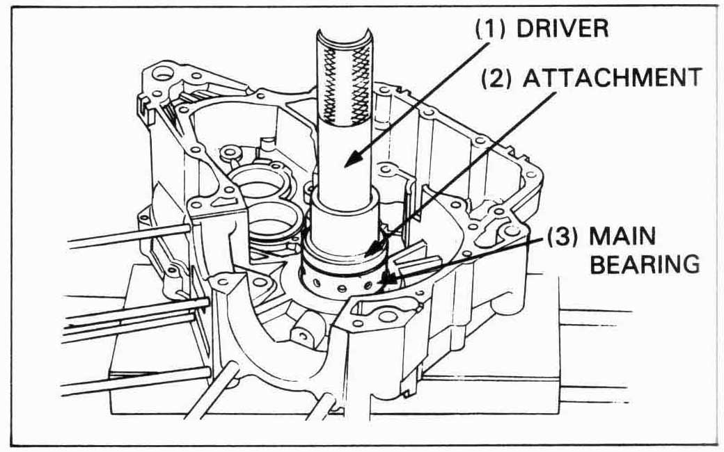
Align the marks on the bearing with the groove in the bearing hole, and press the main bearing into the crankcase.
| TOOLS: | |
| Driver | 07749—0010000 |
| Main bearing driver attachment | 07HMF—MM90400 |

A letter stamped on the connecting rod is the code for the rod’s weight.
When replacing the connectring rod, select the new rod by cross-matching the front and rear cylinder connecting rod weights using the selection table below.
SELECTION TABLE
| A | B | C | D | |
| A | O | O | — | — |
| B | O | O | O | — |
| C | — | O | O | O |
| D | — | — | O | O |
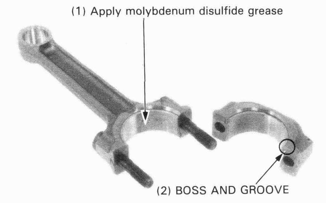
Install the bearing inserts on the rods and caps.
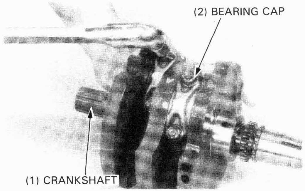
Install the connecting rods and caps on the crankpin. Be sure each part is installed in its original position, as noted during removal.
Tighten the bearing cap nuts.
| TORQUE: | 34 N•m (3.4 kg-m, 25 ft-lb) |
Install the crankshaft in the left crankcase.
Install the dowel pins and assemble the crankcase
(page 11-16).

Remove the mainshaft, countershaft, shift fork shaft and shift drum as an assembly.
Separate the shift forkslshaft, mainshaft and countershaft assemblies from each other.
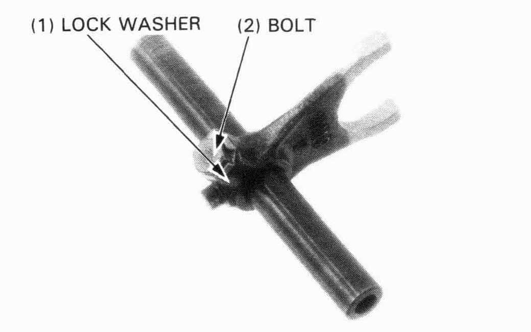
Bend down the lock washer tabs and remove the bolt and lock
washer from the center shift fork.
Remove the shift fork shaft.
Disassemble the mainshaft and countershaft.
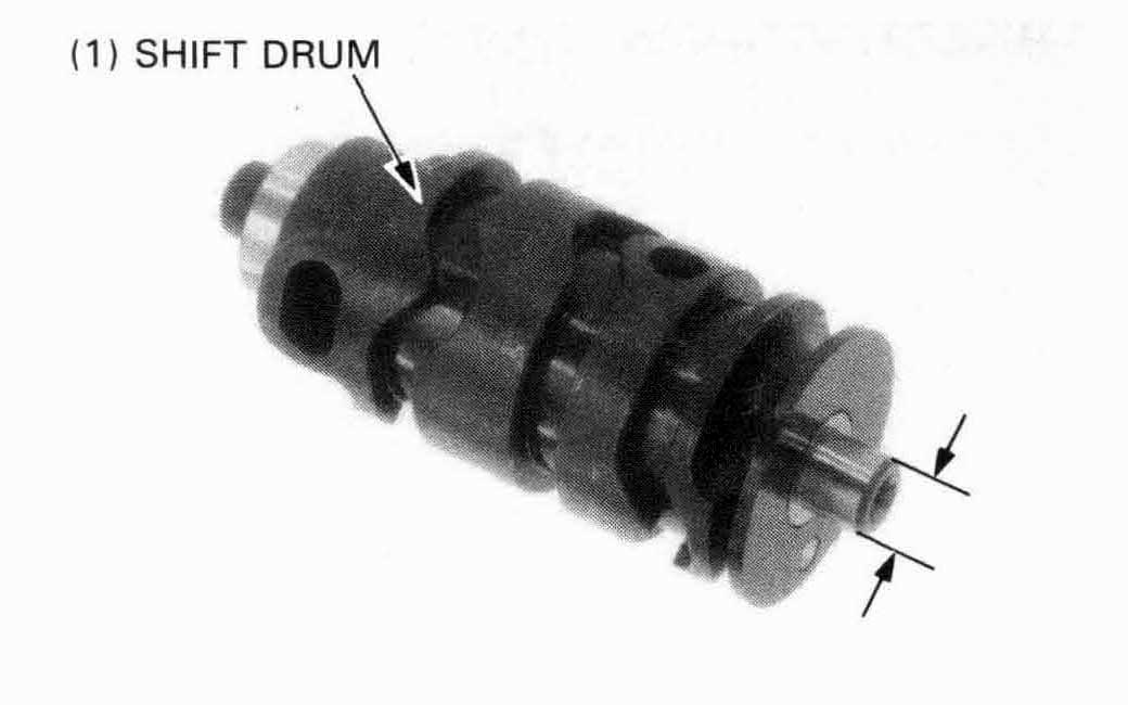
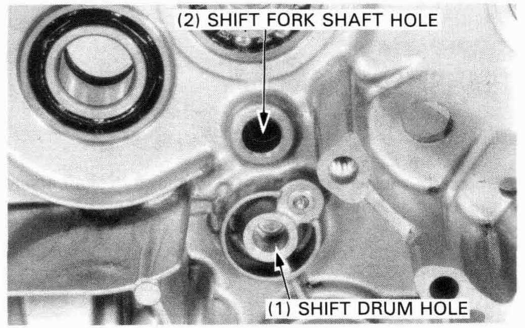
Inspect the shift drum end for scoring, scratches, or evidence of insufficient lubrication. Check the shift drum grooves for damage.
Measure the shift drum shaft O.D. at the left side journal.
| SERVICE LIMIT: | 11.96 mm (0.471 in) |
Check the bearing inner and outer races for damage. The bearing should turn smoothly and quietly.
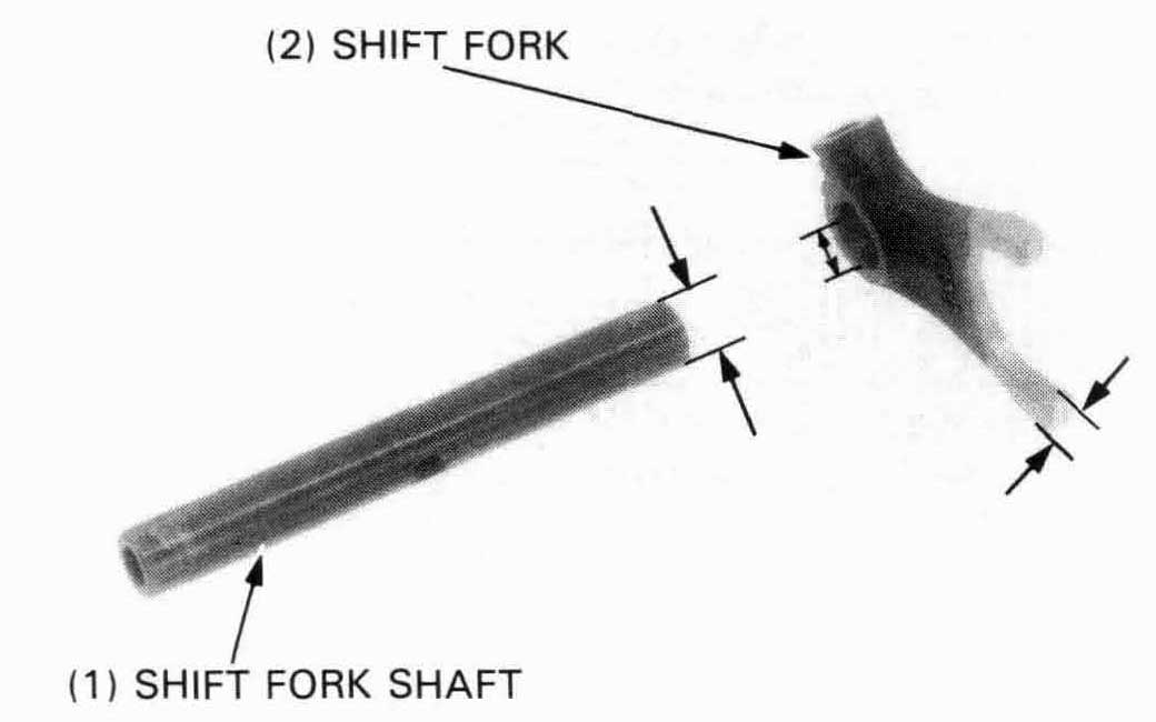
Check the shift fork shaft for scratches, scoring or evidence of
insufficient lubrication.
Measure the shift fork shaft O.D.
| SERVICE LIMIT: | 12.96 mm (0.510 in) |
Measure the I.D. of each shift fork and the fork claw thickness.
| SERVICE LIMITS: | ||
| I.D.: | 13.03 mm (0.513 in) | |
| CLAW THICKNESS: | 5.83 mm (0.230 in) | |
Inspect the shift drum and shift fork shaft journals for exessive wear or damage.
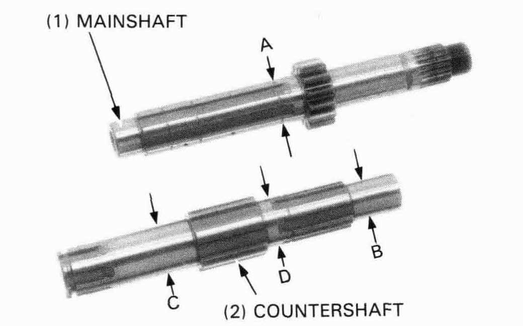
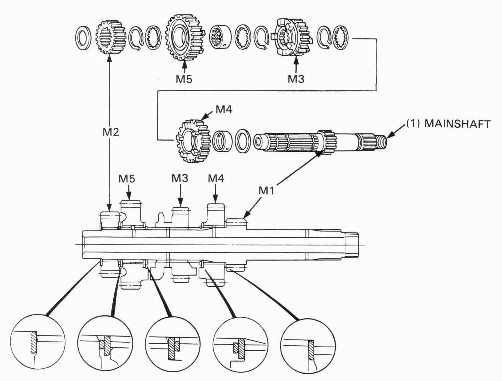
Measure the O.D. of mainshaft and countershaft.
| SERVICE LIMITS: | |
| A: M4 bushing 24.95 mm (0.982 in) | |
| B: C1 bushing 19.97 mm (0.786 in) | |
| C: C2 bushing 24.96 mm (0.983 in) | |
| D: C3 bushing 24.95 mm (0.982 in) | |
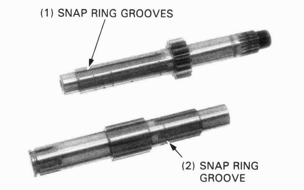
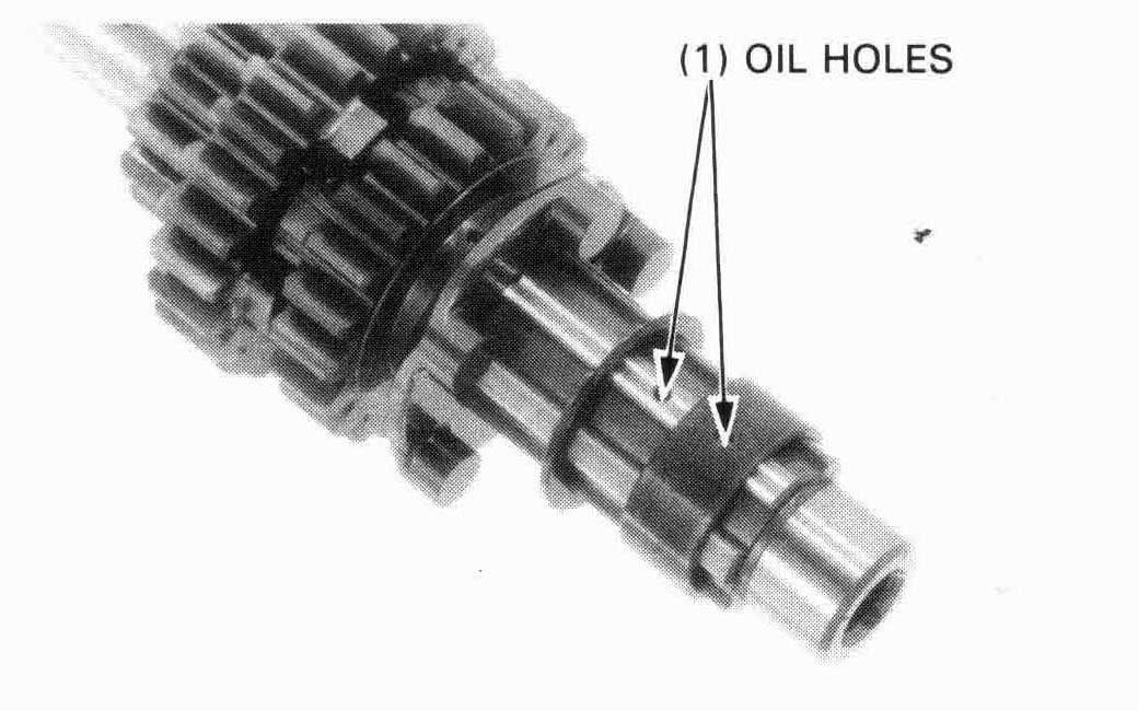
Check each shaft’s grooves for damage.
Replace if necessary.
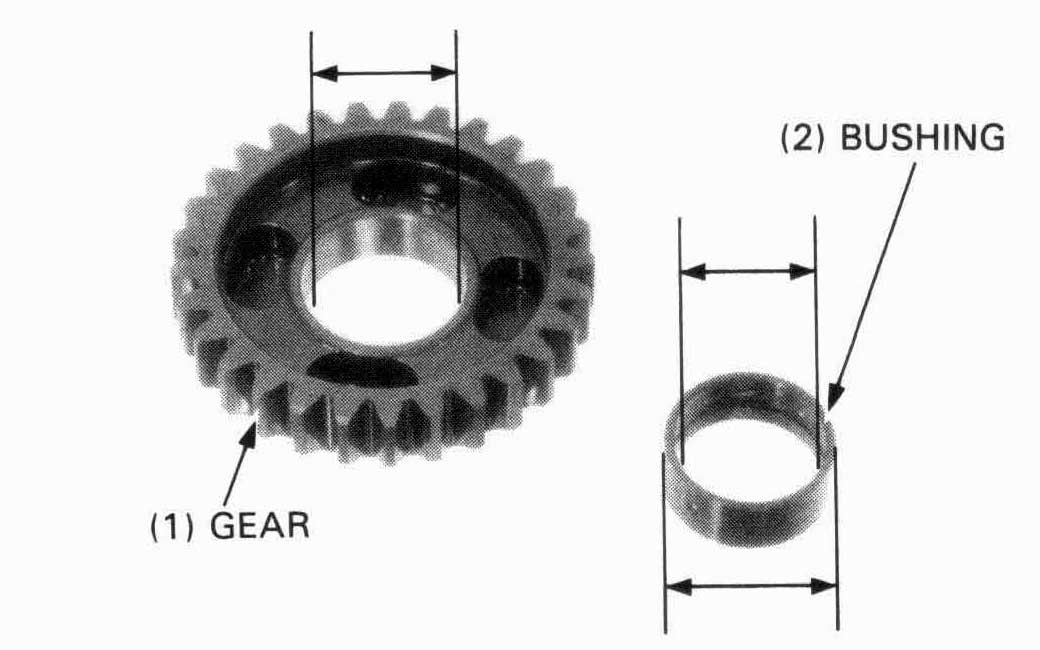
Check the gear dogs, holes and teeth for excessive or
abnormal wear, or evidence of insufficient lubrication.
Meaeasure the I.D. of each gear.
| SERVICE LIMITS: | ||
| M4, M5, C2, C3 gears: | 28.03 mm (1.103 in) | |
| C1 gear: | 24.03 mm (0.946 in) | |
Measure the I.D. and O.D. of each gear bushing.
| SERVICE LIMITS: | |
| M4, M5, C2, C3 bushings O.D.: 27.95 mm (1.100 in) | |
| C1 bushing O.D.: 24.95 mm (0.982 in) | |
| M4, C2, C3 bushing I.D.: 25.03 mm (0.985 in) | |
| C1 bushing I.D.: 20.05 mm (0.789 in) | |
Calculate the bushing to shaft clearances and gear to bushing clearance.
| SERVICE LIMITS: | |
| bushing-to-shaft (M4, C3): | |
| 0.08 mm (0.003 in) | |
| (C2): | |
| 0.07 mm (0.003 in) | |
| gear-to-bushing (M4, M5, C1, C2, C3): | |
| 0.08 mm (0.003 in) | |
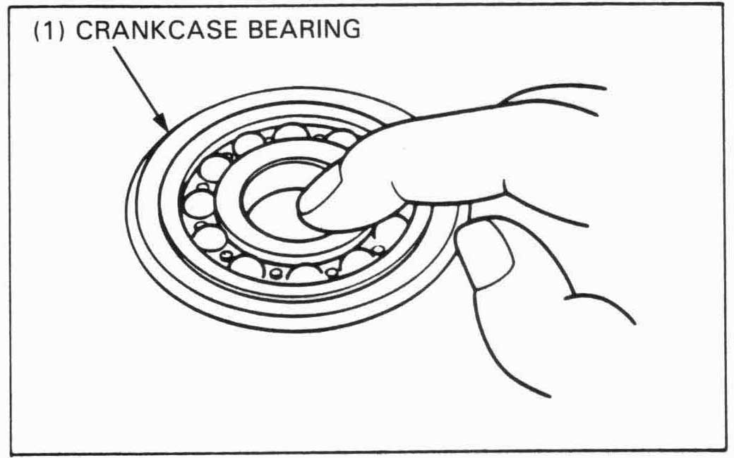
Turn the inner race of each bearing with your finger. The bearings should turn smoothly and quietly. Also check that the bearing outer race fits tightly in the crankcase.
Remove and discard the bearings if the races do not turn smoothly, quietly, or if they fit loosely in the crankcase.
Left crankcase
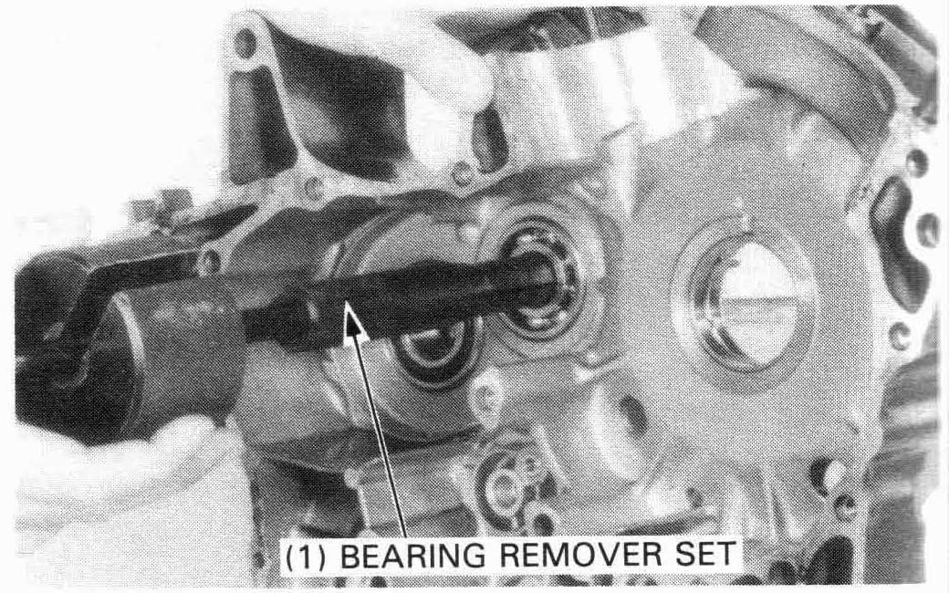
Remove the left mainshaft bearing using the special tools.
| TOOLS: | |
| Bearing remover set | 07936—3710001 |
| — remover handle | 07936—3710100 |
| — bearing remover set | 07936—3710600 |
| — remover weight | 07741—0010201 or 07936—3710200 U.S.A. only |
Drive the countershaft bearing and oil seal out of the crankcase.
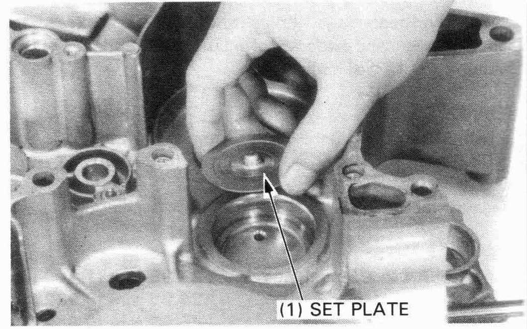
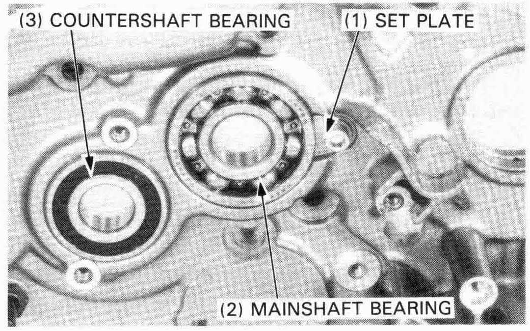
Install the new mainshaft bearing set plate on the left crankcase.
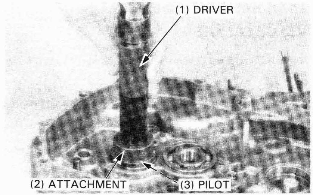
Install the new bearings with the following tools.
| TOOLS: | ||
| Left mainshaft bearing: | ||
| Driver | 07749—0010000 | |
| Attachment, 42 x 47 mm | 07746—0010300 | |
| Left countershaft bearing: | ||
| Driver | 07749—0010000 | |
| Attachment, 52 x 55 mm | 07746—0010400 | |
| Pilot, 25 mm | 07746—0040600 | |
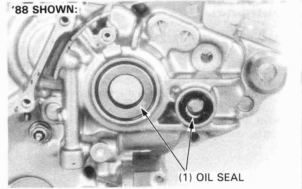
Install a new countershaft oil seal.
Check the gearshift spindle oil seal for wear or damage, replace
if necessary.
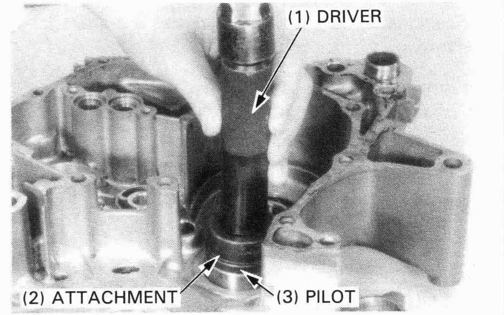
Right crankcase
Remove the mainshaft bearing set plate and drive the
countershaft bearing, mainshaft bearing and shift
drum bearing out of the crankcase.
| TOOLS: | ||
| Sight mainshaft bearing | ||
| Driver | 07749—0010000 | |
| Attachment, 52 x 55 mm | 07746—0010400 | |
| Pilot, 22 mm | 07746—0041000 | |
| Sight countershaft bearing | ||
| Driver | 07749—0010000 | |
| Attachment, 42 x 47 mm | 07746—0010300 | |
| Pilot, 20 mm | 07746—0040500 | |
Apply a locking agent to the threads of the mainshaft bearing set plate attaching bolt.
Install the set plate aligning the edge of the set plate with the slot on the bearing outer and tighten the bolt securely.
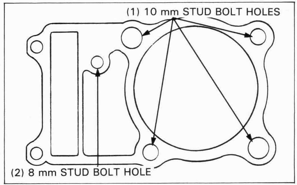
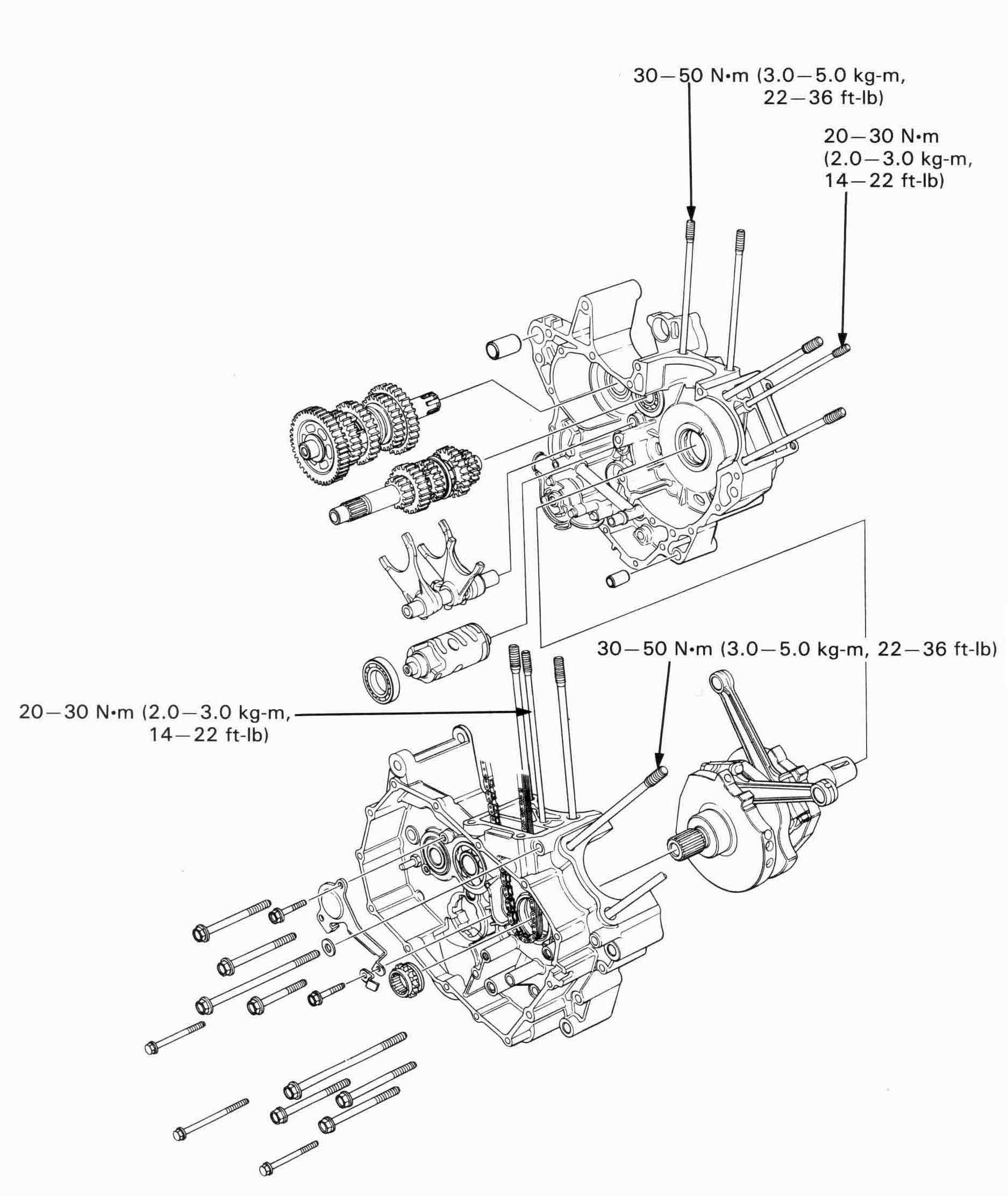
Crankcase studs
Check that the studs are tight. If any are loose, remove them,
clean their threads with contact cleaner, then reinstall them
using Honda Anaerobic Thread Lock, or equivalent.
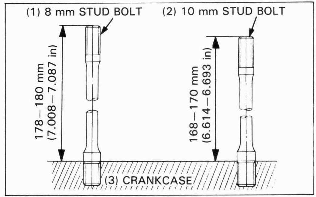
After installing, be sure to measure the distance from the top of each stud to the crankcase surface.
Tighten the stud bolts to the specified torque.
| TORQUE: | 8 mm stud bolt: |
| 20—30 N•m (2.0—3.0 kg-m, 14—22 ft-lb) | |
| 10 mm stud bolt: | |
| 30—50 N•m (3.0—5.0 kg-m, 22—36 ft-lb) |
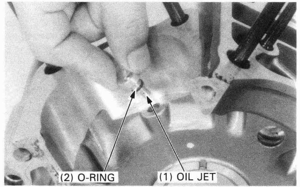
Oil jet
Remove the oil jets from the front cylinder bore of the right and
left crankcase.
Check the O-ring for fatique and damage.
Check the oil jet orifice for clogging.
Apply MoS2 grease to the shift fork journals of MC3, C4 and C5 gears.
Clean all parts in solvent and dip them in clean engine oil.
Mainshaft
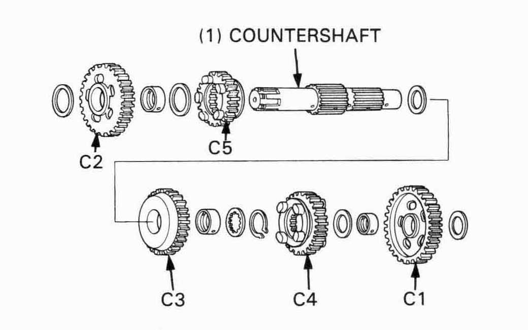
Countershaft
Apply molybdenum disulfide grease to the following.

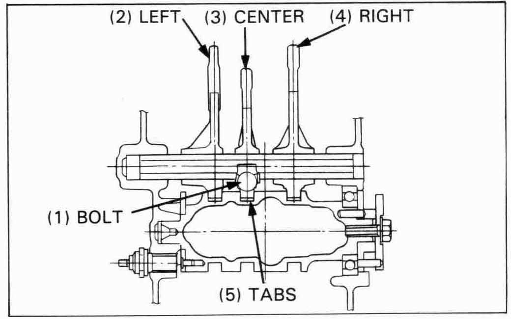
Install the shift forks onto the shaft as follows.
Left side: “MN8L” mark facing R. crankcase.
Center: “C” mark facing L. crankcase.
Right side: “MM9R” mark facing R. crankcase.
Tighten the bolt with the lock washer and bend up the tabs of tie lock washer.
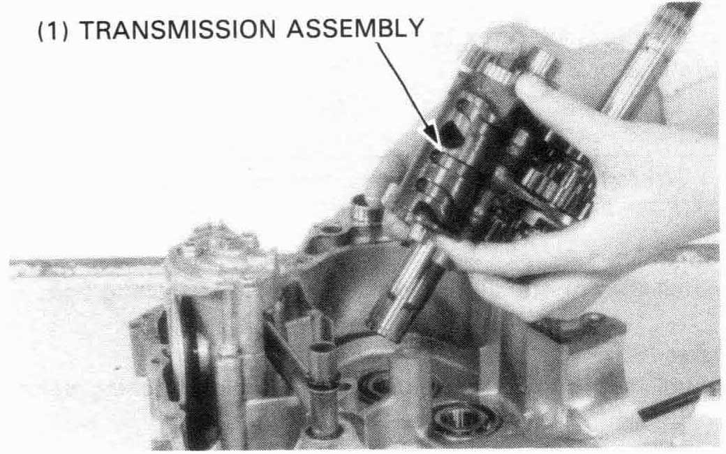
Assemble the mainshaft, countershaft, shift fork shaft and
shift drum.
Install them into the left crankcase as an assembly.

Apply sealant to the crankcase mating surfaces.
Install the dowel pins.
Assemble the right and left crankcases being careful to align the dowel pins and shafts.

Apply oil to all crankcase bolts.
Install and tighten the right crankcase bolts in a crisscross pattern
in 2 or 3 steps.
Install and tighten the left crankcase bolts in a crisscross pattern in 2 or 3 steps.
’88 Only:
Install the countershaft set plate with the attaching bolt.
After ’88:
Install the countershaft set plate with the attaching bolts (2 pcs).
’88, After ’88:
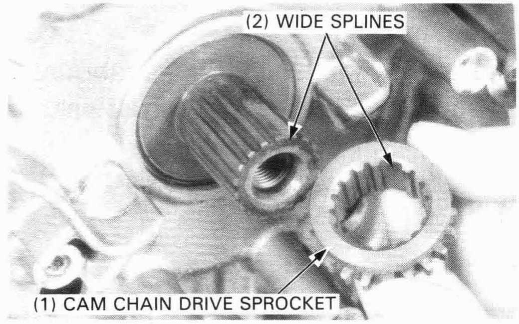
Install the rear cam chain drive sprocket over the crankshaft,
aligning the extra-wide splines in the sprocket and crankshaft.
Install the rear cam chain over the drive sprocket.
Install the oil pipe stay and cam chain tensioner set plate.
Tighten the bolt sercurely.
Install the front cam chain over the front cam chain drive
sprocket.
Install the cam chain tensioner set plate and tighten the bolt
securely.
Install the remaining parts in the reverse order of removal (page 11-3).